 |
Matronics Email Lists
Web Forum Interface to the Matronics Email Lists
|
| View previous topic :: View next topic |
| Author |
Message |
nuckolls.bob(at)aeroelect
Guest
|
 Posted: Sun Aug 30, 2020 6:55 pm Post subject: Revmaster 'dual' alterantors Posted: Sun Aug 30, 2020 6:55 pm Post subject: Revmaster 'dual' alterantors |
 |
|
I've had a few weeks (and road trips) to apply some
'asphalt engineering' effort to a combination of
threads discussing relative fragility of the
Revmaster 'dual' alternators. The latest thread
explored the notion that changing from SLVA to
LiFePO4 was much more likely to burn an alternator winding.
This is not a new topic here on the List . . . found
a few other postings on the same problem.
Without talking to the designers, it's
difficult to KNOW the original thinking behind the
design. We also cannot know what efforts the factory
has applied to this issue over the years. But I
think we're on pretty firm ground to assert that
the current design is marginal with respect to
thermal robustness.
Alternator windings should be as reliable as
propeller bolts. You might smoke some regulators,
trash some batteries, find yourself wanting for a
few more amps of output . . . but suffering destruction
of the windings suggests the alternator is a weak
link in the system.
Based on the drawing that Dan supplied a few weeks
ago it seems that the designers intended that only
one of the two windings be used at the same time.
I'm guessing that this is a "normal-and-spare"
design philosophy. Therefore, any time a winding fails due
to exceedance of thermal limits, the other winding
was off line.
We don't know the internal configuration of the
recommended rectifier/regulator but it's almost
certain to included silicon controlled rectifier
and one diode in series on each conduction half-
cycle. That's 3, silicon junctions in series
that carry alternator output current.
My current hypothesis suggests that it would be
much better to use BOTH windings all the time. Reduce
the current in each winding by 50% or more. It seems
better to have one configuration that's bulletproof
than two relatively fragile configurations that 'back
each other up'.
Here's the line of reasoning supporting this design
goal. Recall the bits-and-pieces of design? (1)
properties of materials, (2) management of energy
and (3)refinement of process. In this case, our
weak link seems to center on an energy management
issue. Some copper windings are heating past
practical operating limits. This can be either
an insulation failure, wire failure or both.
Properties of Materials:
We know that copper has a pretty significant positive
resistance coefficient for temperature. We observed
this in the temperature vs. current observations
in battery contactors:
https://tinyurl.com/mpcgp3t
https://tinyurl.com/k6bwdqo
We also considered the physics of why an overloaded
wire tends to burn open at the center of a free-air
span.
As copper heats up, resistance goes up, voltage drop
goes up, dissipated energy goes up, temperature rises
some more . . . and you can see where this is headed.
Take this tid-bit of knowledge about copper
wire and consider how many times you've observed or
heard of the windings or lead wires of any system
failing due to overheat.
I've seen some windings burn up on alternators for
reasons OTHER than poor thermal management. I've never
had a winding burn on my car. I've had one short
and start popping fuses . . . but I doubt that it
was due to burned insulation or melted wires!
The point is, ANY configuration that demonstrates
repeated failure to do open wires or cooked insulation
is MARGINAL at best; hazardous at worst.
Okay, how to reduce the load in Revmaster alternator
wires . . . hopefully without compromising ability
to deliver ENERGY into the system. Here's the energy
management consideration:
We know that PM alternators have a checkered history
of performance . . . but mostly due to stone simple
regulators that DO NOT offer active current limiting.
Furhter, many versions use a full wave bridge consisting
of two pairs of junction diode and silicon controlled
rectifiers. Alternator output current flows through
two of these devices with total drop on the
order of 2 volts. 2 volts out of a 14v system is
a substantial proportion of energy . . . something
on the order of 15 to 25 watts that needs to be
managed in those cute little castings . . . but
that's another story.
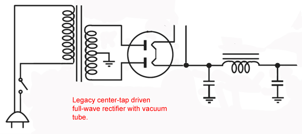
Harking back to the earliest days of my studies
in electron herding, ac rectifiers were vacuum
tubes (not junctions) and ac power sources were transformers
plugged into the wall (not spinning magnets).
Except for the systems with very low energy
requirements (table top radios), the rectifiers
were dual diodes driven from either side of a
center tapped transformer secondary. This configuration
had some profound effects in thermal management.
EACH diode carries 1/2 the total current. These
devices have considerable resistance . . . watts =
I(squared) x R so if you reduce current by 1/2,
watts goes down to 1/4. Same thing happens in the
transformer secondary . . . the secondary wire
size can be made smaller in a trade off between
energy lost and transformer size.
Refinement of process:
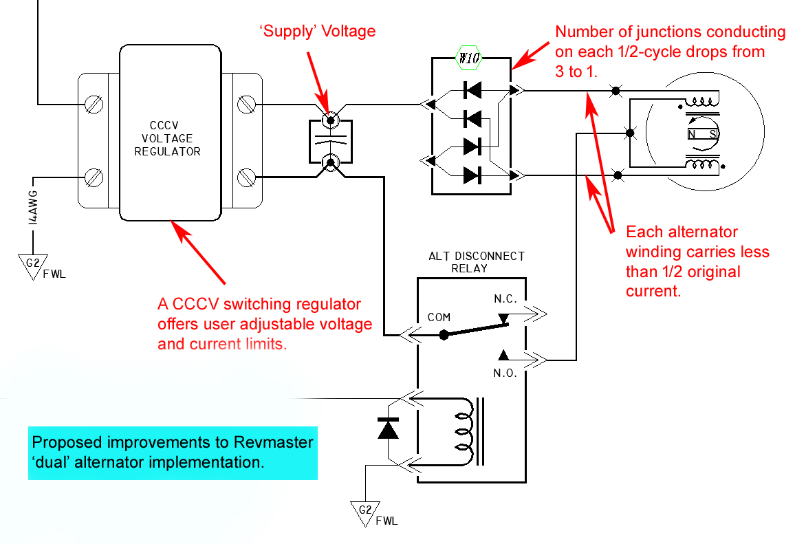
So take a peek at the simplified proposal diagram.
Hook the two Revmaster windings in series-aiding
and bring out the center-tap. Connect in full wave
configuration with only TWO junction rectifiers.
Feed this resulting energy off to a filter capacitor
size to be determined.
This will give us a 'supply voltage' of some value
ideally adjust to about 20VDC at cruise RPM and
alternators full load design point.
This voltage is going to be all over the place
depending on load and engine rpm . . . but that's
the nature of the PM alternator.
Now, let's power condition that energy with a constant
current, constant voltage, switch-mode regulator.
NOW we have a BIG difference in performance:
Voltage is adjustable and controlled by active electronics.
Current is adjustable and limited by active electronics.
I suggest this configuration offers
significant improvement in Revmaster's engine
driven power source. Energy being delivered
to the regulator is at significantly higher than
the output set point, CURRENT in from the alternator
will be LOWER than current delivered by the regulator.
Further, each winding works 1/2 of the time so it
follows that heating effects on each winding are much
reduced from the current configuration.
Silicon junctions in the rectifier are significantly
reduced off-setting some new losses introduced by
the electronic CCCV regulator.
It seems that we could craft an engine driven power
system that almost never fails in exchange for one
that fails too many times and for the wrong reasons.
I'm tied up in some house remodeling and we've
added another grandson to the population of Medicine
Lodge Jr High School . . . so refinement of this idea
will be slow. But I'm building an alternator drive stand,
power supply and load bank out in the mess-making shop. B&C has
provided me with both PM and wound-field test articles.
I have a couple of those CCCV regulators that we discussed
on hand right now. They may not be the right size in all
respects but satisfactory for proof-of-concept experiments. I
already have some LiFePO4 and SLVA batteries on hand.
The pieces are coming together. Comments and considered
critical review are most welcome.
Bob . . .
| | - The Matronics AeroElectric-List Email Forum - | | | Use the List Feature Navigator to browse the many List utilities available such as the Email Subscriptions page, Archive Search & Download, 7-Day Browse, Chat, FAQ, Photoshare, and much more:
http://www.matronics.com/Navigator?AeroElectric-List |
|
| Description: |
|
| Filesize: |
255.18 KB |
| Viewed: |
15420 Time(s) |
|
| Description: |
|
| Filesize: |
100.76 KB |
| Viewed: |
15420 Time(s) |
|
| Description: |
|

Download |
| Filename: |
revmaster_voltage_regulators_516.pdf |
| Filesize: |
57.99 KB |
| Downloaded: |
427 Time(s) |
|
|
| Back to top |
|
 |
user9253
Joined: 28 Mar 2008
Posts: 1975
Location: Riley TWP Michigan
|
| Posted: Mon Aug 31, 2020 7:39 am Post subject: Re: Revmaster 'dual' alterantors |
|
|
Using both windings is a good idea.

What about the phase angle between the two windings?  Do we know what it is?

Suppose the two windings are 90 degrees out of phase or some other unknown angle.

How will that affect the proposed circuit?  Will the peak AC voltage be higher?

Do capacitors help very much to smooth the DC voltage in a power circuit?

It would help to have a Revmaster alternator to play with.
| | - The Matronics AeroElectric-List Email Forum - | | | Use the List Feature Navigator to browse the many List utilities available such as the Email Subscriptions page, Archive Search & Download, 7-Day Browse, Chat, FAQ, Photoshare, and much more:
http://www.matronics.com/Navigator?AeroElectric-List |
|
_________________
Joe Gores |
|
| Back to top |
|
|
nuckolls.bob(at)aeroelect
Guest
|
| Posted: Mon Aug 31, 2020 8:18 am Post subject: Revmaster 'dual' alterantors |
|
|
At 10:39 AM 8/31/2020, you wrote:
| Quote: | --> AeroElectric-List message posted by: "user9253" <fransew(at)gmail.com>
Using both windings is a good idea.
What about the phase angle between the two windings? Do we know what it is? |
No . . .
| Quote: | Suppose the two windings are 90 degrees out of phase or some other unknown angle.
How will that affect the proposed circuit? Will the peak AC voltage be higher? |
Good question.
I doubt they are polyphase . . . you gotta go to a
lot of mechanical fuss to achieve it. It's a function
of stator/magnet ring geometry. They might be different
but it's doubtful. Issue 80 of Contact! magazine has
some nice pictures of the stator arrangement:
http://www.contactmagazine.com/Issue80/Issue-80L.pdf
| Quote: | | Do capacitors help very much to smooth the DC voltage in a power circuit? |
They can . . . it's all about current/capacitance ratio
versus frequency. If a capacitor is necessary, it will
be dictated by the CCCV down converter tolerance for
ripple.
| Quote: | | It would help to have a Revmaster alternator to play with. |
You got that right!
Bob . . .
| | - The Matronics AeroElectric-List Email Forum - | | | Use the List Feature Navigator to browse the many List utilities available such as the Email Subscriptions page, Archive Search & Download, 7-Day Browse, Chat, FAQ, Photoshare, and much more:
http://www.matronics.com/Navigator?AeroElectric-List |
|
|
|
| Back to top |
|
|
echristley(at)att.net
Guest
|
| Posted: Mon Aug 31, 2020 8:36 am Post subject: Revmaster 'dual' alterantors |
|
|
Would this scheme work for other PM generators?  I'm using a 32-amp generator from a Harley-Davidson.  The 74518-88 model regulator for these seems to be as plentiful as light bulbs, but I can't find any good details of what the internals look like.  It has two wire input from the stator, and one wire out to the battery positive.  The case serves as ground. No means of control or way to indicate failure, prompting me to build my own.


                                                                    On Sunday, August 30, 2020, 10:58:25 PM EDT, Robert L. Nuckolls, III <nuckolls.bob(at)aeroelectric.com> wrote:


                 I've had a few weeks (and road trips) to apply some


'asphalt engineering' effort to a combination of


threads discussing relative fragility of the


Revmaster 'dual' alternators. The latest thread


explored the notion that changing from SLVA to


LiFePO4 was much more likely to burn an alternator winding.


This is not a new topic here on the List . . . found


a few other postings on the same problem.


Without talking to the  designers, it's


difficult to KNOW the original thinking behind the


design. We also cannot know what efforts the factory


has applied to this issue over the years. But I


think we're on pretty firm ground to assert that


the current design is marginal with respect to


thermal robustness.


Alternator windings should be as reliable as


propeller bolts. You might smoke some regulators,


trash some batteries, find yourself wanting for a


few more amps of output . . . but suffering destruction


of the windings suggests the alternator is a weak


link in the system.


Based on the drawing that Dan supplied a few weeks


ago it seems that the designers intended that only


one of the two windings be used at the same time.


I'm guessing that this is a "normal-and-spare"


design philosophy. Therefore, any time a winding fails due


to exceedance of thermal limits, the other winding


was off line.


We don't know the internal configuration of the


recommended rectifier/regulator but it's almost


certain to included silicon controlled rectifier


and one diode in series on each conduction half-


cycle. That's 3, silicon junctions in series


that carry alternator output current.


My current hypothesis suggests that it would be


much better to use BOTH windings all the time. Reduce


the current in each winding by 50% or more. It seems


better to have one configuration that's bulletproof


than two relatively fragile configurations that 'back


each other up'.


Here's the line of reasoning supporting this design


goal. Recall the bits-and-pieces of design? (1)


properties of materials, (2) management of energy


and (3)refinement of process. In this case, our


weak link seems to center on an energy management


issue. Some copper windings are heating past


practical operating limits. This can be either


an insulation failure, wire failure or both.


Properties of Materials:


We know that copper has a pretty significant positive


resistance coefficient for temperature. We observed


this in the temperature vs. current observations


in battery contactors:


https://tinyurl.com/mpcgp3t


https://tinyurl.com/k6bwdqo


We also considered the physics of why an overloaded


wire tends to burn open at the center of a free-air


span.


As copper heats up, resistance goes up, voltage drop


goes up, dissipated energy goes up, temperature rises


some more . . . and you can see where this is headed.


Take this tid-bit of knowledge about copper


wire and consider how many times you've observed or


heard of the windings or lead wires of any system


failing due to overheat.


I've seen some windings burn up on alternators for


reasons OTHER than poor thermal management. I've never


had a winding burn on my car. I've had one short


and start popping fuses . . . but I doubt that it


was due to burned insulation or melted wires!


The point is, ANY configuration that demonstrates


repeated failure to do open wires or cooked insulation


is MARGINAL at best; hazardous at worst.


Okay, how to reduce the load in Revmaster alternator


wires . . . hopefully without compromising ability


to deliver ENERGY into the system. Here's the energy


management consideration:


We know that PM alternators have a checkered history


of performance . . . but mostly due to stone simple


regulators that DO NOT offer active current limiting.


Furhter, many versions use a full wave bridge consisting


of two pairs of junction diode and silicon controlled


rectifiers. Alternator output current flows through


two of these devices with total drop on the


order of 2 volts. 2 volts out of a 14v system is


a substantial proportion of energy . . . something


on the order of 15 to 25 watts that needs to be


managed in those cute little castings . . . but


that's another story.


Harking back to the earliest days of my studies


in electron herding, ac rectifiers were vacuum


tubes (not junctions) and ac power sources were transformers


plugged into the wall (not spinning magnets).


Except for the systems with very low energy


requirements (table top radios), the rectifiers


were dual diodes driven from either side of a


center tapped transformer secondary. This configuration


had some profound effects in thermal management.


EACH diode carries 1/2 the total current. These


devices have considerable resistance . . . watts =


I(squared) x R so if you reduce current by 1/2,


watts goes down to 1/4.  Same thing happens in the


transformer secondary . . . the secondary wire


size can be made smaller in a trade off between


energy lost and transformer size.


Refinement of process:


So take a peek at the simplified proposal diagram.


Hook the two Revmaster windings in series-aiding


and bring out the center-tap. Connect in full wave


configuration with only TWO junction rectifiers.


Feed this resulting energy off to a filter capacitor


size to be determined.


This will give us a 'supply voltage' of some value


ideally adjust to about 20VDC at cruise RPM and


alternators full load design point.


This voltage is going to be all over the place


depending on load and engine rpm . . . but that's


the nature of the PM alternator.


Now, let's power condition that energy with a constant


current, constant voltage, switch-mode regulator.


NOW we have a BIG difference in performance:


Voltage is adjustable and controlled by active electronics.


Current is adjustable and limited by active electronics.


I suggest this configuration offers


significant improvement in Revmaster's engine


driven power source. Energy being delivered


to the regulator is at significantly higher than


the output set point, CURRENT in from the alternator


will be LOWER than current delivered by the regulator.


Further, each winding works 1/2 of the time so it


follows that heating effects on each winding are much


reduced from the current configuration.


Silicon junctions in the rectifier are significantly


reduced off-setting some new losses introduced by


the electronic CCCV regulator.


It seems that we could craft an engine driven power


system that almost never fails in exchange for one


that fails too many times and for the wrong reasons.


I'm tied up in some house remodeling and we've


added another grandson to the population of Medicine


Lodge Jr High School . . . so refinement of this idea


will be slow. But I'm building an alternator drive stand,


power supply and load bank out in the mess-making shop. B&C has


provided me with both PM and wound-field test articles.


I have a couple of those CCCV regulators that we discussed


on hand right now. They may not be the right size in all


respects but satisfactory for proof-of-concept experiments. I


already have some LiFePO4 and SLVA batteries on hand.


The pieces are coming together. Comments and considered


critical review are most welcome.


   Bob . . .
| | - The Matronics AeroElectric-List Email Forum - | | | Use the List Feature Navigator to browse the many List utilities available such as the Email Subscriptions page, Archive Search & Download, 7-Day Browse, Chat, FAQ, Photoshare, and much more:
http://www.matronics.com/Navigator?AeroElectric-List |
|
|
|
| Back to top |
|
|
dj_theis
Joined: 28 Aug 2017
Posts: 68
Location: Minnesota
|
| Posted: Thu Sep 03, 2020 7:14 pm Post subject: Re: Revmaster 'dual' alterantors |
|
|
>>Without talking to the designers, it's


>>difficult to KNOW the original thinking behind the


>>design.


I've spoken to Joe Horvoth a couple of times, before and just after purchasing my engine. I spoke to him at least once regarding the alternator and ignition system.  Joe is not a particularly "chatty" fella but I think he is rightly proud of his design. His innovation in the design and improvements of the VW are truly impressive.  Joe is clearly gifted when it comes to mechanical design and engine building. Unfortunately, I think the electrical systems were done by a hired gun and not by Joe directly (an unconfirmed rumor I am starting).


As noted in the earlier posts and comments, Joe has strongly recommended not to run both alternator sides at the same time and has also strongly discouraged the use of anything but traditional lead acid (wet) batteries.  I've never heard him go into any detail on the reasons behind these recommendations.  I should have asked when I visited him a few years back.


>>So take a peek at the simplified proposal diagram.

>>Hook the two Revmaster windings in series-aiding

>>and bring out the center-tap. Connect in full wave

>>configuration with only TWO junction rectifiers.


I like the approach and two questions come to mind:

 How well the current will be equally divided by the two windings?

  This is half wave rectification, right?


I have not spun my engine yet but from examination of the windings I expect to see the two PMAs "IN PHASE" and as noted, single phase, not polyphase.  Does this configuration change the expectation of roughly evenly divided current?  If the two PMAs were out of phase by 180 degrees (which is possible if my talents with the "right hand rule" are off abit) I assume the center tap would not operate the same, if at all.


I have to pull my engine once more before I start it (hopefully, yet this fall) and will examine the windings on the PMAs closely to convince myself of the phase relationship between the two halves.


One final note.  I've thought about this a little (clearly not as much as Bob). I plan on installing thermo-couples as close to the center of each stator base as I can.  My thought is to run the engine as deigned, with OEM regulators and running one halve at a time.  I am planning on a Odyssey battery (PC680) with added (2) shunt resistors in the charge circuit to increase the load seen by the PMAs.  I plan on trying to identify what the conditions are that lead to the high temperature in the PMAs.  I hope to be able to install the TCs close enough to the windings to obtain a warning before they overheat.  I think the expected meltdown of the "enamel" insulation is a bit over 200C.  Can anyone confirm?


In the long term, I'd like to install something like the CCCV regulator mentioned.  Is there actually such a regulator designed and available for a PMA on an OBAM aircraft?


Dan Theis
| | - The Matronics AeroElectric-List Email Forum - | | | Use the List Feature Navigator to browse the many List utilities available such as the Email Subscriptions page, Archive Search & Download, 7-Day Browse, Chat, FAQ, Photoshare, and much more:
http://www.matronics.com/Navigator?AeroElectric-List |
|
_________________
Dan Theis
Scratch building Sonex #1362
Revmaster Alternator problem solved. |
|
| Back to top |
|
|
user9253
Joined: 28 Mar 2008
Posts: 1975
Location: Riley TWP Michigan
|
| Posted: Fri Sep 04, 2020 5:22 am Post subject: Re: Revmaster 'dual' alterantors |
|
|
Actually it is desired that the two windings be 180 degrees out of phase.

That way, only one winding will conduct at a time and the output will be pulsing

DC.  If the two windings are in phase, no problem, just reverse the leads on

one of the windings.  Then the windings will be 180 degrees out of phase.
| | - The Matronics AeroElectric-List Email Forum - | | | Use the List Feature Navigator to browse the many List utilities available such as the Email Subscriptions page, Archive Search & Download, 7-Day Browse, Chat, FAQ, Photoshare, and much more:
http://www.matronics.com/Navigator?AeroElectric-List |
|
_________________
Joe Gores |
|
| Back to top |
|
|
nuckolls.bob(at)aeroelect
Guest
|
| Posted: Fri Sep 04, 2020 5:28 am Post subject: Revmaster 'dual' alterantors |
|
|
| Quote: | >>So take a peek at the simplified proposal diagram.
>>Hook the two Revmaster windings in series-aiding
>>and bring out the center-tap. Connect in full wave
>>configuration with only TWO junction rectifiers.
I like the approach and two questions come to mind:
How well the current will be equally divided by the two windings?
This is half wave rectification, right? |
No, full wave . . . the current doesn't
NEED to be exactly shared . . . each winding
conduct on 1/2 cycle of the time independently
of each other. Unlike the legacy, single winding
PMA and bridge rectifier approach, this
configuration splits the two halves onto
separate windings . . . but it's still
full wave rectification.
| Quote: | | I have not spun my engine yet but from examination of the windings I expect to see the two PMAs "IN PHASE" and as noted, single phase, not polyphase. Does this configuration change the expectation of roughly evenly divided current? If the two PMAs were out of phase by 180 degrees (which is possible if my talents with the "right hand rule" are off abit) I assume the center tap would not operate the same, if at all. |
From what I understand, the Revmaster
PMA is wound BI-FILAR meaning two strands
of wire side-by-by side. This produces
two, identical windings that COULD and
perhaps SHOULD be wired in parallel. This
would cut the current in each winding to
1/2 of the total.
| Quote: | | I have to pull my engine once more before I start it (hopefully, yet this fall) and will examine the windings on the PMAs closely to convince myself of the phase relationship between the two halves. |
The result is predictable. You have two, identical
windings sharing the same physical space
on the stator. Voltages induced by the
mechanics and magnetics are identical.
Given that the burning the 'active' winding
also burns the 'standby' winding, you do
not have redundant systems. You might as
well run the two windings in parallel
which would greatly reduce the stress on
the wires and may well drive the 'lithium'
failure rate to zero.
| Quote: | | One final note. I've thought about this a little (clearly not as much as Bob). I plan on installing thermo-couples as close to the center of each stator base as I can. My thought is to run the engine as deigned, with OEM regulators and running one halve at a time. I am planning on a Odyssey battery (PC680) with added (2) shunt resistors in the charge circuit to increase the load seen by the PMAs. I plan on trying to identify what the conditions are that lead to the high temperature in the PMAs. I hope to be able to install the TCs close enough to the windings to obtain a warning before they overheat. I think the expected meltdown of the "enamel" insulation is a bit over 200C. Can anyone confirm? |
I don't know of any manufacturer of aviation
hardware that doesn't call out Class H insulation
for their magnet wire
https://tinyurl.com/y3a7o26s
Without going to some exotic wire coated
with un-obtainium, Class H is the best
you can buy off the shelf. So yeah, 200C
max operating for the copper . . .
Thermocoupling the windings is not a bad idea.
Are those stator windings varnished? Getting
a 'real' copper temperature number on a running
machine is not easy. The closest I ever
got to 'real' measurements was by bringing
leads for winding-under-observation outside
so that it could be quickly switched from
'service' to 'measure' mode by exciting the
winding with a calibrated current and then
measuring the voltage drop. Copper temperature
can be calculated by knowing the temperature coefficient
of resistance for copper. This had to be done
quickly (under 100 mS) 'cause the copper cools
very rapidly when the loads are removed and the
heat soaks out.
Generally speaking, with your 200C rated wire,
getting thermocouple readings over 170-180C
would be cause for concern.
We KNOW this design is thermally deficient . . .
too many of them have burned up in service.
Too many band-aids have been suggested
and attempted with little if any relief.
| Quote: | | In the long term, I'd like to install something like the CCCV regulator mentioned. Is there actually such a regulator designed and available for a PMA on an OBAM aircraft? |
Sure, they're commercial off the shelf items.
I've got a couple on the bench now that I'm
going to use in a proof-of-concept study. But
after reading about the bi-filar windings
design, I'm not sure there's much value to
be secured by 'upgrading' the rectifier/regulator
design for this engine.
As currently configured, there is NO REDUNDANCY
of engine driven power sources. I'm beginning
to think one would be well advised to
simply parallel the two windings and treat
them as one. This alone would produce a profound
drop in wire temperatures for any given load.
Bob . . .
| | - The Matronics AeroElectric-List Email Forum - | | | Use the List Feature Navigator to browse the many List utilities available such as the Email Subscriptions page, Archive Search & Download, 7-Day Browse, Chat, FAQ, Photoshare, and much more:
http://www.matronics.com/Navigator?AeroElectric-List |
|
|
|
| Back to top |
|
|
dj_theis
Joined: 28 Aug 2017
Posts: 68
Location: Minnesota
|
| Posted: Fri Sep 04, 2020 6:25 pm Post subject: Re: Revmaster 'dual' alterantors |
|
|
[quote]

Actually it is desired that the two windings be 180 degrees out of phase.

That way, only one winding will conduct at a time and the output will be pulsing

DC. If the two windings are in phase, no problem, just reverse the leads on

one of the windings. Then the windings will be 180 degrees out of phase.

[/quote]


Ah, yes.  that makes perfect sense.  The end result is a full wave rectified waveform output.


Thanks for the clarification Joe.


Dan Theis.[/quote]
| | - The Matronics AeroElectric-List Email Forum - | | | Use the List Feature Navigator to browse the many List utilities available such as the Email Subscriptions page, Archive Search & Download, 7-Day Browse, Chat, FAQ, Photoshare, and much more:
http://www.matronics.com/Navigator?AeroElectric-List |
|
_________________
Dan Theis
Scratch building Sonex #1362
Revmaster Alternator problem solved. |
|
| Back to top |
|
|
dj_theis
Joined: 28 Aug 2017
Posts: 68
Location: Minnesota
|
| Posted: Sat Sep 05, 2020 6:38 pm Post subject: Re: Revmaster 'dual' alterantors |
|
|
Bob,  for some reason your post made it to me on the digest but does not show up on the forum (as far as I can find).  You posted it just before Joe on Friday morning (I think).  It begins as follows:


>> >>So take a peek at the simplified proposal diagram.

>> >>Hook the two Revmaster windings in series-aiding

>> >>and bring out the center-tap. Connect in full wave

>> >>configuration with only TWO junction rectifiers.

>

>>I like the approach and two questions come to mind:

>>  How well the current will be equally divided by the two windings?

>>   This is half wave rectification, right?


 >  No, full wave . . . the current doesn't

 >  NEED to be exactly shared . . . each winding

 >  conduct on 1/2 cycle of the time independently

 >  of each other. Unlike the legacy, single winding

 >  PMA and bridge rectifier approach, this

 > configuration splits the two halves onto

 >  separate windings . . . but it's still

 > full wave rectification


OK, I've convinced myself that the OEM design made use of 1/2 wave rectification.  Unless I'm wrong on this, running both sides with the OEM rectifiers (which is discouraged) would have the same current (total) heat generation as this very elegant center tap as you've shown.


The other issue is heat from the engine.  I have to wonder if the real culprit is not the windings at all but the proximity of the PMAs to the crankcase heat.


If we consider the report on the Onex where both sides failed (burned) when only one was operating, perhaps it is the engine heat and inability to reject that, along with the PMAs internal heating that conspire against us.


Not to throw another apple into the barrel but can we effectively add a blast tube to the environment around the PMAs?


As far as I can see, there is one tiny little inlet hole for ventilation from above the engine into the PMA area.  This hole is mostly covered by the flywheel.  Not much of any opportunity to reject heat other than conduction through the surface of the casting at the back of the engine.


Dan Theis
| | - The Matronics AeroElectric-List Email Forum - | | | Use the List Feature Navigator to browse the many List utilities available such as the Email Subscriptions page, Archive Search & Download, 7-Day Browse, Chat, FAQ, Photoshare, and much more:
http://www.matronics.com/Navigator?AeroElectric-List |
|
_________________
Dan Theis
Scratch building Sonex #1362
Revmaster Alternator problem solved. |
|
| Back to top |
|
|
N509RV(at)eckenroth.com
Guest
|
| Posted: Wed Sep 09, 2020 5:44 am Post subject: Revmaster 'dual' alterantors |
|
|
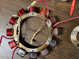
I think that there might be a misunderstanding of the Revmaster architecture in that I don't believe that the windings for the two generators are in tandem but are a series of 5 coils each for two generators.  I have enclosed a picture of the stator from my friend's engine. He was running one generator at the time and you can see how severely it was destroyed. The Phenolic base was also destroyed. The second generator coils don't look bad but they are also ruined. To me one of the interesting things is that the ignition coils are still functional.  My primary purpose in starting this thread was to hopefully end up with a definite fix for the problem. Trying this or that is not practicable due to the destructive nature of the overheating. The stator is over $500 to replace and requires pulling the engine to do so. I'll only really know that the problem is fixed when the smoke stays in the coils.Â
It seems to me that the most important change will be to use the B&C AVC1 volltage regulator since it is designed for firewall forward and can be adjusted down to 13.7 v which is the minimum voltage that will fully charge the EarthX battery. With the voltage reduction should come current reduction. What I don't know (and hopefully the educated on the list can explain) is whether restricting the voltage will also restrict the current. Can the generator still create abnormal current and therefore heat. I will try and incorporate thermocouples in with the coils but I'm not sure how much advance warning they can give.
So, with the new voltage regulator set at 13.7 can the generator still pump out current based on engine speed and battery resistance or is the current capped since the voltage is restricted. I'm trying to determine if I have a good chance of success here.
Does anybody want to redesign the generator to make it more robust.
Paul
On Mon, Aug 31, 2020 at 12:25 PM Robert L. Nuckolls, III <nuckolls.bob(at)aeroelectric.com (nuckolls.bob(at)aeroelectric.com)> wrote:
| Quote: | At 10:39 AM 8/31/2020, you wrote:
| Quote: | --> AeroElectric-List message posted by: "user9253" <fransew(at)gmail.com (fransew(at)gmail.com)>
Using both windings is a good idea.
What about the phase angle between the two windings? Do we know what it is? |
 No . . .
| Quote: | Suppose the two windings are 90 degrees out of phase or some other unknown angle.Â
How will that affect the proposed circuit? Will the peak AC voltage be higher? |
Â
 Good question.
 I doubt they are polyphase . . . you gotta go to a
 lot of mechanical fuss to achieve it. It's a function
 of stator/magnet ring geometry. They might be different
 but it's doubtful. Issue 80 of Contact! magazine has
 some nice pictures of the stator arrangement:
http://www.contactmagazine.com/Issue80/Issue-80L.pdf
| Quote: | | Do capacitors help very much to smooth the DC voltage in a power circuit? |
 They can . . . it's all about current/capacitance ratio
 versus frequency. If a capacitor is necessary, it will
 be dictated by the CCCV down converter tolerance for
 ripple.
| Quote: | | It would help to have a Revmaster alternator to play with. |
 You got that right!
 Bob . . .
|
| | - The Matronics AeroElectric-List Email Forum - | | | Use the List Feature Navigator to browse the many List utilities available such as the Email Subscriptions page, Archive Search & Download, 7-Day Browse, Chat, FAQ, Photoshare, and much more:
http://www.matronics.com/Navigator?AeroElectric-List |
|
|
|
| Back to top |
|
|
user9253
Joined: 28 Mar 2008
Posts: 1975
Location: Riley TWP Michigan
|
| Posted: Wed Sep 09, 2020 9:14 am Post subject: Re: Revmaster 'dual' alterantors |
|
|
Current is not capped.  Current is determined by the load.  The load takes

what it wants.  Some loads such as batteries and resistance type loads will

take less current when the voltage drops.  Loads with switching power

supplies will take more current as the voltage drops because they operate with

constant power.  Many modern avionics have switching power supplies.

Lowering the voltage will reduce the EarthX battery charging current.
| | - The Matronics AeroElectric-List Email Forum - | | | Use the List Feature Navigator to browse the many List utilities available such as the Email Subscriptions page, Archive Search & Download, 7-Day Browse, Chat, FAQ, Photoshare, and much more:
http://www.matronics.com/Navigator?AeroElectric-List |
|
_________________
Joe Gores |
|
| Back to top |
|
|
ceengland7(at)gmail.com
Guest
|
| Posted: Wed Sep 09, 2020 10:52 am Post subject: Revmaster 'dual' alterantors |
|
|
On 9/9/2020 12:14 PM, user9253 wrote:
| Quote: |
Current is not capped. Current is determined by the load. The load takes
what it wants. Some loads such as batteries and resistance type loads will
take less current when the voltage drops. Loads with switching power
supplies will take more current as the voltage drops because they operate with
constant power. Many modern avionics have switching power supplies.
Lowering the voltage will reduce the EarthX battery charging current.
--------
Joe Gores
Ohm's Law sets the current. The battery has a source impedance when
|
supplying energy, and it has a load impedance when being charged. The
battery mfgr should be able to tell you the battery's load impedance
while charging (ask for worst case). That number, and the charge
voltage, will give you the charging current. Off-the-shelf 'smart'
battery chargers manage current by adjusting voltage 'on the fly',
tailored to optimum charge rates for a particular battery.
If I were dealing with a 'locked in' flaky design like the Revmaster,
I'd be looking at using a constant current source between the
alternator-regulator and the rest of the airframe. With lithium tech
being found everywhere now, constant voltage/constant current
(misleading term...) battery chargers are everywhere at very reasonable
prices. By inserting one between the regulator's output and the
airframe's bus, you can set the current limit in the charging module at
a point lower than the 'at risk' point for your alternator.
BTW, with a $500 price point, I'd be finding the original source for
that armature. That style alternator is used in dozens (hundreds?) of
products. I'd bet that with a little research, you could find that model
from the actual mfgr for a lot less money. If not, I'd be finding a way
to install an external alternator. I wouldn't be able to stand it. 
Charlie
--
This email has been checked for viruses by Avast antivirus software.
https://www.avast.com/antivirus
| | - The Matronics AeroElectric-List Email Forum - | | | Use the List Feature Navigator to browse the many List utilities available such as the Email Subscriptions page, Archive Search & Download, 7-Day Browse, Chat, FAQ, Photoshare, and much more:
http://www.matronics.com/Navigator?AeroElectric-List |
|
|
|
| Back to top |
|
|
echristley(at)att.net
Guest
|
| Posted: Wed Sep 09, 2020 2:29 pm Post subject: Revmaster 'dual' alterantors |
|
|
Well, for $500 you could rewind the stator by hand, and use a heavier gauge wire.
I don't understand why this would be so expensive. You can get the entire charging system for a Harley for around $150.
Sent from AT&T Yahoo Mail on Android
| Quote: | On Wed, Sep 9, 2020 at 6:45, Paul Eckenroth
<N509RV(at)eckenroth.com> wrote:
I think that there might be a misunderstanding of the Revmaster architecture in that I don't believe that the windings for the two generators are in tandem but are a series of 5 coils each for two generators. I have enclosed a picture of the stator from my friend's engine. He was running one generator at the time and you can see how severely it was destroyed. The Phenolic base was also destroyed. The second generator coils don't look bad but they are also ruined. To me one of the interesting things is that the ignition coils are still functional. My primary purpose in starting this thread was to hopefully end up with a definite fix for the problem. Trying this or that is not practicable due to the destructive nature of the overheating. The stator is over $500 to replace and requires pulling the engine to do so. I'll only really know that the problem is fixed when the smoke stays in the coils.
It seems to me that the most important change will be to use the B&C AVC1 volltage regulator since it is designed for firewall forward and can be adjusted down to 13.7 v which is the minimum voltage that will fully charge the EarthX battery. With the voltage reduction should come current reduction. What I don't know (and hopefully the educated on the list can explain) is whether restricting the voltage will also restrict the current. Can the generator still create abnormal current and therefore heat. I will try and incorporate thermocouples in with the coils but I'm not sure how much advance warning they can give.
So, with the new voltage regulator set at 13.7 can the generator still pump out current based on engine speed and battery resistance or is the current capped since the voltage is restricted. I'm trying to determine if I have a good chance of success here.
Does anybody want to redesign the generator to make it more robust.
Paul
On Mon, Aug 31, 2020 at 12:25 PM Robert L. Nuckolls, III <nuckolls.bob(at)aeroelectric.com (nuckolls.bob(at)aeroelectric.com)> wrote:
| Quote: | At 10:39 AM 8/31/2020, you wrote:
| Quote: | --> AeroElectric-List message posted by: "user9253" <fransew(at)gmail.com (fransew(at)gmail.com)>
Using both windings is a good idea.
What about the phase angle between the two windings? Do we know what it is? |
No . . .
| Quote: | Suppose the two windings are 90 degrees out of phase or some other unknown angle.
How will that affect the proposed circuit? Will the peak AC voltage be higher? |
Good question.
I doubt they are polyphase . . . you gotta go to a
lot of mechanical fuss to achieve it. It's a function
of stator/magnet ring geometry. They might be different
but it's doubtful. Issue 80 of Contact! magazine has
some nice pictures of the stator arrangement:
http://www.contactmagazine.com/Issue80/Issue-80L.pdf
| Quote: | | Do capacitors help very much to smooth the DC voltage in a power circuit? |
They can . . . it's all about current/capacitance ratio
versus frequency. If a capacitor is necessary, it will
be dictated by the CCCV down converter tolerance for
ripple.
| Quote: | | It would help to have a Revmaster alternator to play with. |
You got that right!
Bob . . .
|
|
| | - The Matronics AeroElectric-List Email Forum - | | | Use the List Feature Navigator to browse the many List utilities available such as the Email Subscriptions page, Archive Search & Download, 7-Day Browse, Chat, FAQ, Photoshare, and much more:
http://www.matronics.com/Navigator?AeroElectric-List |
|
|
|
| Back to top |
|
|
nuckolls.bob(at)aeroelect
Guest
|
| Posted: Thu Sep 10, 2020 5:50 am Post subject: Revmaster 'dual' alterantors |
|
|
At 08:43 AM 9/9/2020, you wrote:
| Quote: | I think that there might be a misunderstanding of the Revmaster
architecture in that I don't believe that the windings for the
two generators are in tandem but are a series of 5 coils each
for two generators. |
Hmmmm . . . if that's the case, then it's probably
accurate to call it a 'dual' alternator system . . .
or perhaps 1/2 + 1/2 alternators system.
The energy generation potential for these alternators
is a function of the magnetics/mechanics. Magnet
strength, magnetic cross-section of the stator
and rotor, permeability of the steels, air gaps
between moving parts, rates of change for
magnetic lines of force acting on the windings (rpm)
and a few other little details like losses in
the steels and windings.
Bottom line is that by dividing the two windings
between stator 'halves', the ability to do
the mechanical to electrical energy conversion
for each alternator is about 1/2 that of the
potential whole.
It would seem more practical to have all
the stator magnetics to participate in the
energy conversion efforts using fewer turns
per pole of heavier wire. One might then
achieve more robustness and more energy
output at the same time.
| Quote: | | I have enclosed a picture of the stator from my friend's engine. |
I don't see that image . . . how did you 'enclose'
it?
| Quote: | It seems to me that the most important change will be to use the B&C AVC1
volltage regulator since it is designed for firewall forward and can be
adjusted down to 13.7 v which is the minimum voltage that will fully charge
the EarthX battery. With the voltage reduction should come current reduction. |
Probably not. Keep in mind that as you rotate of the
runway into the blue, there are two kinds of loads
on your alternator. Battery recharge + system running
loads. The TOTAL of these two values is exceeding
the alternator's limitations for thermal management
and has not much to do with the bus voltage set-point.
The fact that an EarthX battery seems to exacerbate
the failure rate only speaks to that battery's
lower internal resistance and willingness to accept
charge at a lower voltage than SLVA.
I.e. the LiFEPO4 battery is NOT ROOT CAUSE of the
unhappy condition . . . only a slightly greater
stress on the alternator seems to exacerbate
failure rates. Adjusting the voltage down by
exploiting the features of the AVC1 might
reduce the failure rate but I kinda doubt it.
I've got a fully discharged ETX36D on the bench
that I'll try to plot the recharge profile when
impressed with a 13.7V set-point. But I'm
confident that an adjustable regulator will not
'fix' fundamental shortcomings of the alternator.
| Quote: | What I don't know (and hopefully the educated on the list can explain)
is whether restricting the voltage will also restrict the current. |
Maybe a little
| Quote: | | Can the generator still create abnormal current and therefore heat. |
You betcha . . . but system loads are much more
significant than characteristics of the battery.
| Quote: | I will try and incorporate thermocouples in with the coils but I'm
not sure how much advance warning they can give. |
Lots of warning. Those wires don't smoke in tens
of milliseconds like fuses. The insulation degrades
over time . . . probably hours of operation at
temperatures exceeding design limits of the INSULATION.
I think this system would benefit greatly by some
extensive testing on a drive stand to optimize
wire size and turns against instrumented performance
measurements. The SD8 from B&C got tested with about
a half dozen exploratory configurations before the
final configuration went to production.
I'd like to see the performance characteristics
of the existing stator wound with fewer turns
of fatter wires on ALL available energy
production poles.
Bob . . .
| | - The Matronics AeroElectric-List Email Forum - | | | Use the List Feature Navigator to browse the many List utilities available such as the Email Subscriptions page, Archive Search & Download, 7-Day Browse, Chat, FAQ, Photoshare, and much more:
http://www.matronics.com/Navigator?AeroElectric-List |
|
|
|
| Back to top |
|
|
nuckolls.bob(at)aeroelect
Guest
|
| Posted: Thu Sep 10, 2020 7:25 am Post subject: Revmaster 'dual' alterantors |
|
|
At 05:25 PM 9/9/2020, you wrote:
| Quote: | | Well, for $500 you could rewind the stator by hand, and use a heavier gauge wire. |
THAT would be a really good experiment!
Bob . . .
| | - The Matronics AeroElectric-List Email Forum - | | | Use the List Feature Navigator to browse the many List utilities available such as the Email Subscriptions page, Archive Search & Download, 7-Day Browse, Chat, FAQ, Photoshare, and much more:
http://www.matronics.com/Navigator?AeroElectric-List |
|
|
|
| Back to top |
|
|
dj_theis
Joined: 28 Aug 2017
Posts: 68
Location: Minnesota
|
| Posted: Thu Sep 10, 2020 8:36 am Post subject: Re: Revmaster 'dual' alterantors |
|
|
| nuckolls.bob(at)aeroelect wrote: | At 08:43 AM 9/9/2020, you wrote:
| Quote: | I think that there might be a misunderstanding of the Revmaster
architecture in that I don't believe that the windings for the
two generators are in tandem but are a series of 5 coils each
for two generators. |
Hmmmm . . . if that's the case, then it's probably
accurate to call it a 'dual' alternator system . . .
or perhaps 1/2 + 1/2 alternators system.
| Quote: | | I have enclosed a picture of the stator from my friend's engine. |
I don't see that image . . . how did you 'enclose'
it?
|
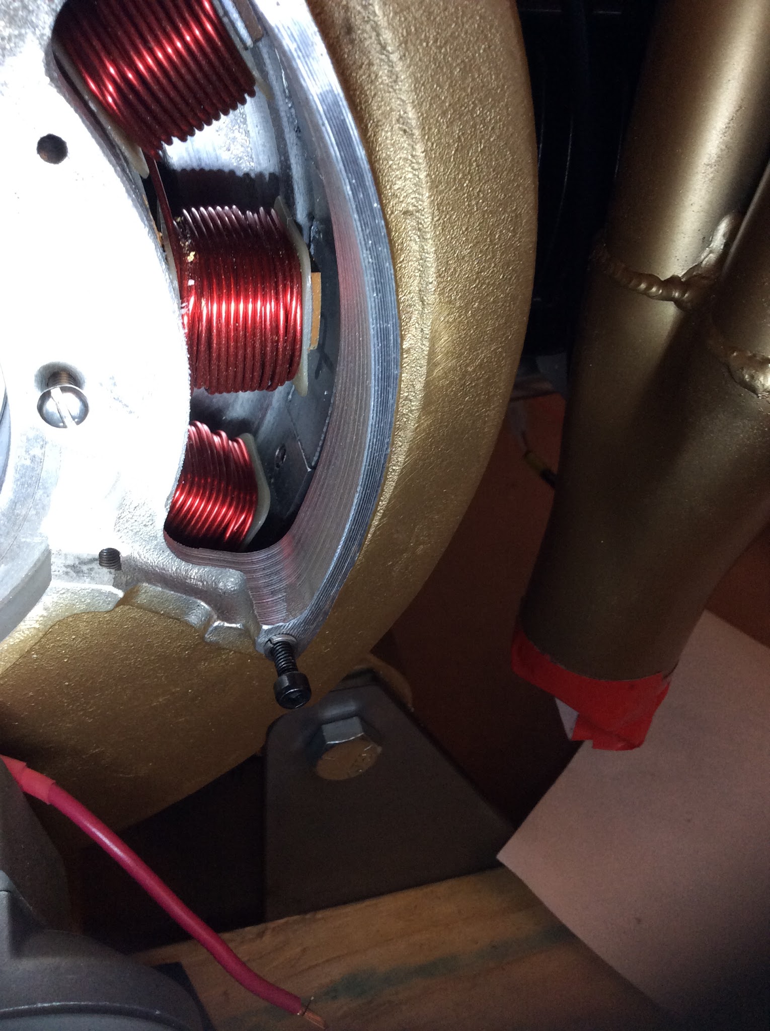
Images as attachments of the R2300 from when I first received my engine in 2017.
There are two separate stator windings, 5 coils on each stator with relatively large wires (12 AWG ?). Next time I pull the engine, I'll mic the wires on the coils.
Note, setting this up as a center tap as suggested should be straight forward. Again I have to state that I think the average current with your center tap arrangement will be the same as the OEM half wave R/R with both sides enabled.
| Quote: |
I think this system would benefit greatly by some
extensive testing on a drive stand to optimize
wire size and turns against instrumented performance
measurements. The SD8 from B&C got tested with about
a half dozen exploratory configurations before the
final configuration went to production.
I'd like to see the performance characteristics
of the existing stator wound with fewer turns
of fatter wires on ALL available energy
production poles.
Bob . . . |
I will try to obtain some fundamental characteristics of the alternators within the next 30 days. (i.e. short circuit current, open circuit voltage at starter rpm, inductance...).
Let me point out the obvious,... "redesigning this system puts the builder in a situation of complete ownership of the problem as it is doubtful Revmaster will support a modified system." The OBAM pilot takes on that responsibility (or should he/she does) regardless of the OEM support, so maybe that is not worth mentioning.
Adding an external alternator is not obvious (to me) where it would mount but earlier versions of the engine had external alternators (I believe), so the design components could be available Revmaster. I amazed (concerned) that with the close proximity of the CDI power coils and ignition electronics that there are no reported failures of that system, related to the alternator failures. makes me want to consider returning to 2 mags and an external alternator for the R2300. Again, maybe easier said the executed but certainly a design that was once available.
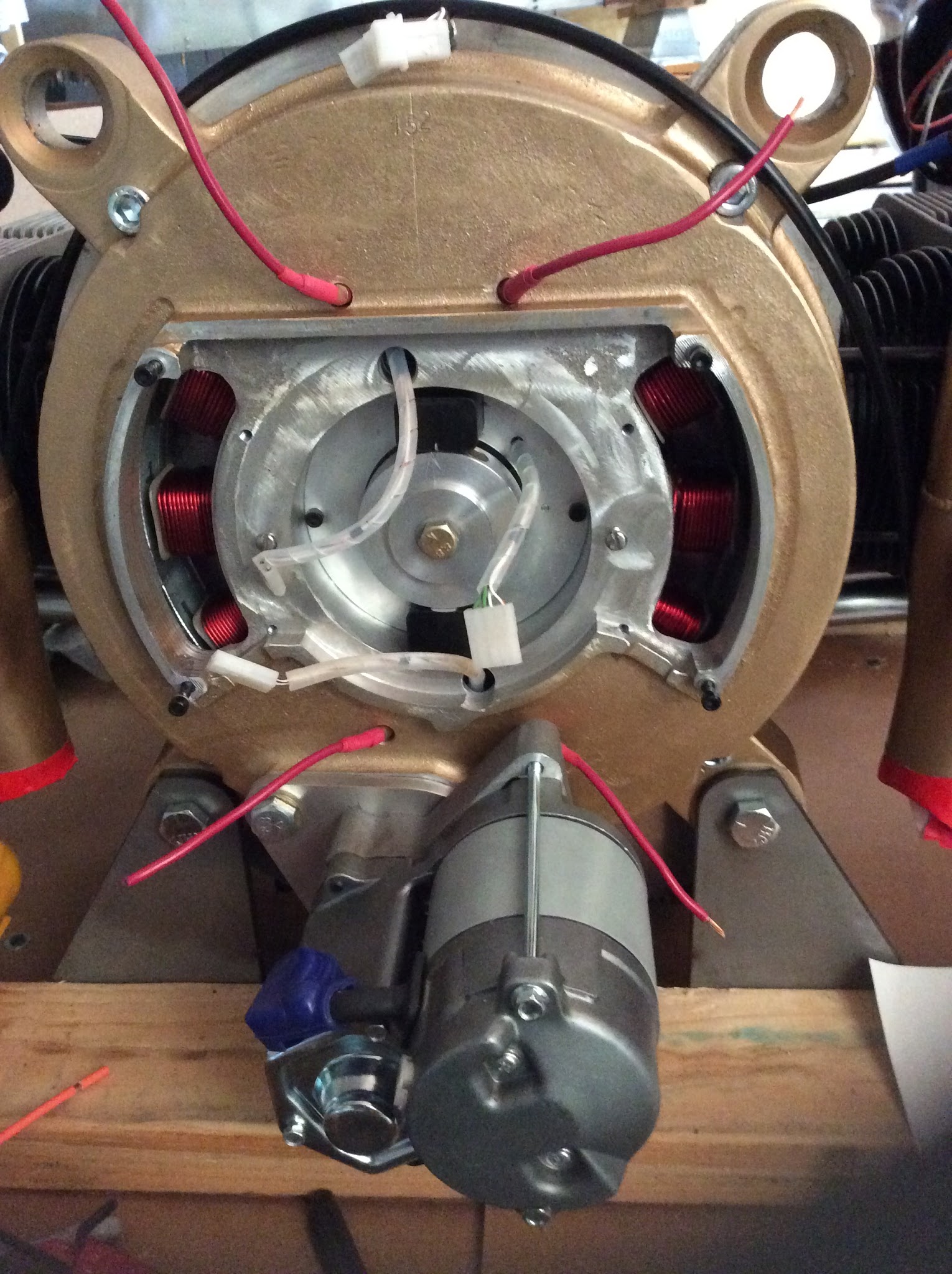
One thing that puzzles me though. At least one failure of BOTH alternators, as reported by Eric or Paul, occurred with only one alternator activated. How is it possible to overheat both sides simultaneously (through heat conduction I have to assume) without damaging the ingnition coils that sit between the two alternators ??
(Molex connectors and wires in my photo from the two ignition coils and the timing signals are shown).
I have to suspect there is another heat source or cause that is contributing to these PMA failures. Engine heat?
Dan Theis
| | - The Matronics AeroElectric-List Email Forum - | | | Use the List Feature Navigator to browse the many List utilities available such as the Email Subscriptions page, Archive Search & Download, 7-Day Browse, Chat, FAQ, Photoshare, and much more:
http://www.matronics.com/Navigator?AeroElectric-List |
|
| Description: |
| Close up of right side alternator windings |
|
| Filesize: |
442.58 KB |
| Viewed: |
15222 Time(s) |
|
| Description: |
| Back of engine alternator with CDI ignition box removed |
|
| Filesize: |
477.85 KB |
| Viewed: |
15222 Time(s) |
|
_________________
Dan Theis
Scratch building Sonex #1362
Revmaster Alternator problem solved. |
|
| Back to top |
|
|
user9253
Joined: 28 Mar 2008
Posts: 1975
Location: Riley TWP Michigan
|
| Posted: Thu Sep 10, 2020 9:07 am Post subject: Re: Revmaster 'dual' alterantors |
|
|
There are 4 black screws in the picture that look like they might hold a cover

on.  Is it possible to pipe pressurized air into that cover to cool the coils?

If the coils were kept cool, their ampacity would be greatly increased.
| | - The Matronics AeroElectric-List Email Forum - | | | Use the List Feature Navigator to browse the many List utilities available such as the Email Subscriptions page, Archive Search & Download, 7-Day Browse, Chat, FAQ, Photoshare, and much more:
http://www.matronics.com/Navigator?AeroElectric-List |
|
_________________
Joe Gores |
|
| Back to top |
|
|
N509RV(at)eckenroth.com
Guest
|
| Posted: Thu Sep 10, 2020 12:23 pm Post subject: Revmaster 'dual' alterantors |
|
|
Hopefully here is the image of the stator that I thought was sent previously.
Paul
On Thu, Sep 10, 2020 at 12:51 PM dj_theis <djtheis58(at)gmail.com (djtheis58(at)gmail.com)> wrote:
| Quote: | --> AeroElectric-List message posted by: "dj_theis" <djtheis58(at)gmail.com (djtheis58(at)gmail.com)>
nuckolls.bob(at)aeroelect wrote:
> At 08:43 AM 9/9/2020, you wrote:
>Â
> > I think that there might be a misunderstanding of the Revmaster
> >Â architecture in that I don't believe that the windings for the
> >Â two generators are in tandem but are a series of 5 coils each
> >Â for two generators.
>
>Â Â Hmmmm . . . if that's the case, then it's probably
>Â Â accurate to call it a 'dual' alternator system . . .
>Â Â or perhaps 1/2 + 1/2 alternators system.
>
>Â Â
>Â
> >Â I have enclosed a picture of the stator from my friend's engine.
>
>Â Â I don't see that image . . . how did you 'enclose'
>Â Â it?
>
>
Images as attachments of the R2300 from when I first received my engine in 2017.
There are two separate stator windings, 5 coils on each stator with relatively large wires (12 AWG ?). Next time I pull the engine, I'll mic the wires on the coils.Â
Note, setting this up as a center tap as suggested should be straight forward. Again I have to state that I think the average current with your center tap arrangement will be the same as the OEM half wave R/R with both sides enabled.
>
>Â Â I think this system would benefit greatly by some
>Â Â extensive testing on a drive stand to optimize
>Â Â wire size and turns against instrumented performance
>Â Â measurements. The SD8 from B&C got tested with about
>Â Â a half dozen exploratory configurations before the
>Â Â final configuration went to production.
>
>Â Â I'd like to see the performance characteristics
>Â Â of the existing stator wound with fewer turns
>Â Â of fatter wires on ALL available energy
>Â Â production poles.
>
>Â
>Â
>Â Â Bob . . .
I will try to obtain some fundamental characteristics of the alternators within the next 30 days. (i.e. short circuit current, open circuit voltage at starter rpm, inductance...).
Let me point out the obvious,... "redesigning this system puts the builder in a situation of complete ownership of the problem as it is doubtful Revmaster will support a modified system."Â The OBAM pilot takes on that responsibility (or should he/she does) regardless of the OEM support, so maybe that is not worth mentioning.
 Adding an external alternator is not obvious (to me) where it would mount but earlier versions of the engine had external alternators (I believe), so the design components could be available Revmaster. I amazed (concerned) that with the close proximity of the CDI power coils and ignition electronics that there are no reported failures of that system, related to the alternator failures. makes me want to consider returning to 2 mags and an external alternator for the R2300. Again, maybe easier said the executed but certainly a design that was once available.
One thing that puzzles me though. At least one failure of BOTH alternators, as reported by Eric or Paul, occurred with only one alternator activated. How is it possible to overheat both sides simultaneously (through heat conduction I have to assume) without damaging the ingnition coils that sit between the two alternators ??
(Molex connectors and wires in my photo from the two ignition coils and the timing signals are shown).
I have to suspect there is another heat source or cause that is contributing to these PMA failures. Engine heat?
Dan Theis
--------
Scratch building Sonex #1362
Read this topic online here:
http://forums.matronics.com/viewtopic.php?p=498299#498299
Attachments:
http://forums.matronics.com//files/20200910_154510000_ios_107.jpg
http://forums.matronics.com//files/20200910_152443000_ios_116.jpg
===========
-
Electric-List" rel="noreferrer" target="_blank">http://www.matronics.com/Navigator?AeroElectric-List
===========
FORUMS -
eferrer" target="_blank">http://forums.matronics.com
===========
WIKI -
errer" target="_blank">http://wiki.matronics.com
===========
b Site -
     -Matt Dralle, List Admin.
rel="noreferrer" target="_blank">http://www.matronics.com/contribution
===========
|
| | - The Matronics AeroElectric-List Email Forum - | | | Use the List Feature Navigator to browse the many List utilities available such as the Email Subscriptions page, Archive Search & Download, 7-Day Browse, Chat, FAQ, Photoshare, and much more:
http://www.matronics.com/Navigator?AeroElectric-List |
|
| Description: |
|
| Filesize: |
23.9 KB |
| Viewed: |
15201 Time(s) |
|
|
|
| Back to top |
|
|
dj_theis
Joined: 28 Aug 2017
Posts: 68
Location: Minnesota
|
| Posted: Thu Sep 10, 2020 12:47 pm Post subject: Re: Revmaster 'dual' alterantors |
|
|
| user9253 wrote: | There are 4 black screws in the picture that look like they might hold a cover
on. Is it possible to pipe pressurized air into that cover to cool the coils?
If the coils were kept cool, their ampacity would be greatly increased. |
It is possible and I agree it's worth considering. I'll look at the CDI eletronics casting (which is what those screws hold in place) to see if there is a pathway to generate an inlet and egress for air. I don't have any good photos of the inside of that casting. Maybe I can pull that casting off without pulling the engine. I'll look tonight.
Thanks for the suggestion.
Dan Theis
| | - The Matronics AeroElectric-List Email Forum - | | | Use the List Feature Navigator to browse the many List utilities available such as the Email Subscriptions page, Archive Search & Download, 7-Day Browse, Chat, FAQ, Photoshare, and much more:
http://www.matronics.com/Navigator?AeroElectric-List |
|
_________________
Dan Theis
Scratch building Sonex #1362
Revmaster Alternator problem solved. |
|
| Back to top |
|
|
nuckolls.bob(at)aeroelect
Guest
|
| Posted: Thu Sep 10, 2020 1:21 pm Post subject: Revmaster 'dual' alterantors |
|
|
At 03:18 PM 9/10/2020, you wrote:
| Quote: | Hopefully here is the image of the stator that I thought was sent previously.
Paul |
Excellent . . . thank you. I agree, this definitely
appears to be a PAIR of 5-pole alternators.
Good data point.
Bob . . .
| | - The Matronics AeroElectric-List Email Forum - | | | Use the List Feature Navigator to browse the many List utilities available such as the Email Subscriptions page, Archive Search & Download, 7-Day Browse, Chat, FAQ, Photoshare, and much more:
http://www.matronics.com/Navigator?AeroElectric-List |
|
|
|
| Back to top |
|
|
|
|
You cannot post new topics in this forum
You cannot reply to topics in this forum
You cannot edit your posts in this forum
You cannot delete your posts in this forum
You cannot vote in polls in this forum
You cannot attach files in this forum
You can download files in this forum
|
Powered by phpBB © 2001, 2005 phpBB Group
|

