 |
Matronics Email Lists
Web Forum Interface to the Matronics Email Lists
|
| View previous topic :: View next topic |
| Author |
Message |
nuckolls.bob(at)aeroelect
Guest
|
 Posted: Wed Sep 20, 2023 6:46 pm Post subject: OVM14 MkIII, rev P1 Posted: Wed Sep 20, 2023 6:46 pm Post subject: OVM14 MkIII, rev P1 |
 |
|
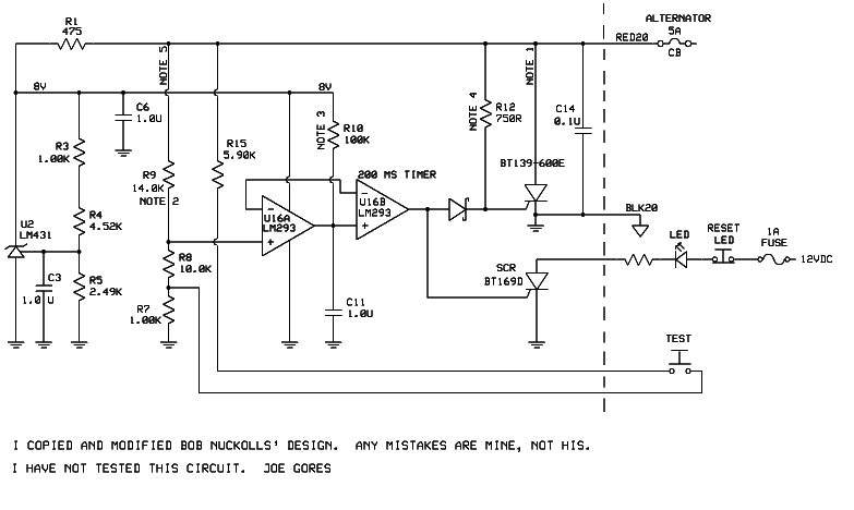
Here 'tis.


 You guys with sharp pencils and greased calculators

 are encouraged to flush out the 'bugs'.


   Bob . . .


                    ////

                   (o o)

    ===========o00o=(_)=o00o=========

    < Go ahead, make my day . . .   >

    < show me where I'm wrong.      >

    =================================


    In the interest of creative evolution

    of the-best-we-know-how-to-do based

    on physics and good practice.
| | - The Matronics AeroElectric-List Email Forum - | | | Use the List Feature Navigator to browse the many List utilities available such as the Email Subscriptions page, Archive Search & Download, 7-Day Browse, Chat, FAQ, Photoshare, and much more:
http://www.matronics.com/Navigator?AeroElectric-List |
|
| Description: |
|

Download |
| Filename: |
9003-620-1P1,_OVM-14_Mk_III,_SCHEMATIC.pdf |
| Filesize: |
156.17 KB |
| Downloaded: |
1101 Time(s) |
|
|
| Back to top |
|
 |
Eric Page
Joined: 15 Feb 2017
Posts: 244
|
| Posted: Fri Sep 22, 2023 11:50 am Post subject: Re: OVM14 MkIII, rev P1 |
|
|
A few things that I noticed...
1. Absolute maximum cathode-to-anode voltage on the LM431 is 37V (see TI and onsemi datasheets). A significant OV event could exceed that limit until the crowbar brings bus voltage under control. This might not be an issue with a lead-acid battery, but the OV behavior of the BMS in lithium batteries is unknown. If a lithium BMS disconnects pronto, bus voltage could rise farther and more quickly than with lead-acid on the job.
Q: Should there be a 33V Zener in parallel to protect the LM431?
-----
2. The recommended maximum voltage on LM293 inputs is Vcc minus 2V (see table 6.2 in the TI datasheet). In this case Vcc is 8V, so the max input voltage is 6V.
- The 7V reference exceeds 6V on the inverting inputs of both comparators.
- Any bus voltage >13.64V will exceed 6V on the non-inverting input of U16A.
- Timing capacitor C11 on the non-inverting input of U16B will charge to 8V.
Q: Should the comparator reference be adjusted downward (perhaps delete R4, adjust R3/R5, and use the LM431's 2.5V reference for the comparators)?
Q: Should the non-inverting inputs be protected with 5.1V Zeners?
-----
3. In recent discussion of the OVM task you mentioned your intent to make the trip delay 500mS +/- 50mS. This schematic provides ~200mS.
Q: Have you reconsidered the 500mS trip delay?
-----
4. Schematic Note 1 contemplates a crowbar current of 100-200A DC for 25mS. The BT139-600E SCR datasheet shows a peak non-repetitive on-state current of 155A, but that specification assumes an initial junction temperature of 25degC (unlikely under an engine cowling), a pulse duration â¤20mS and a full-sine-wave AC pulse, not DC.
Q: Can the BT139-600E handle this crowbar task? If not, could you swap U16B's inputs and interpose a P-FET to trigger a beefier SCR?
-----
Could you describe how to calculate the effect of closing the PTT switch (connecting 5.9kΩ from 8V to the junction of R8 and R7)? I'm at a loss as to how that works; it might as well be witchcraft! Thanks.
| | - The Matronics AeroElectric-List Email Forum - | | | Use the List Feature Navigator to browse the many List utilities available such as the Email Subscriptions page, Archive Search & Download, 7-Day Browse, Chat, FAQ, Photoshare, and much more:
http://www.matronics.com/Navigator?AeroElectric-List |
|
|
|
| Back to top |
|
|
user9253
Joined: 28 Mar 2008
Posts: 1910
Location: Riley TWP Michigan
|
| Posted: Sat Sep 23, 2023 2:33 pm Post subject: Re: OVM14 MkIII, rev P1 |
|
|
I think that most people would expect the crowbar overvoltage device to trip

the breaker when the push-to-test button is pressed, regardless of whether

the alternator is running or not, especially during an annual condition inspection

by a mechanic or new owner.
| | - The Matronics AeroElectric-List Email Forum - | | | Use the List Feature Navigator to browse the many List utilities available such as the Email Subscriptions page, Archive Search & Download, 7-Day Browse, Chat, FAQ, Photoshare, and much more:
http://www.matronics.com/Navigator?AeroElectric-List |
|
_________________
Joe Gores |
|
| Back to top |
|
|
nuckolls.bob(at)aeroelect
Guest
|
| Posted: Sat Sep 23, 2023 3:49 pm Post subject: OVM14 MkIII, rev P1 |
|
|
At 05:33 PM 9/23/2023, you wrote:
| Quote: | --> AeroElectric-List message posted by: "user9253" <fransew(at)gmail.com>
I think that most people would expect the crowbar overvoltage device to trip
the breaker when the push-to-test button is pressed, regardless of whether
the alternator is running or not, especially during an annual condition inspection
by a mechanic or new owner. |
The product would be supplied with instructions
calling out a procedure for validating
continued airworthiness. Leave the button
off if you will. Do not label it anything.
At a propitious time verification procedures
say, join the two wires together. Start
the engine leaving alternator OFF. Field
breaker should remain closed. Turn alternator
ON. Breaker should open. Shut down engine.
Disconnect the two wires and secure for
service.
The procedure not only verifies gross
functionality but makes a good ball-
park check of calibration. A push
button precludes inadvertently leaving
them together . . . but you'd know
about it early on when the alternator
fails to stay on line . . . so it's
pretty much fail-passive either
way.
Bob . . .
////
(o o)
===========o00o=(_)=o00o=========
< Go ahead, make my day . . . >
< show me where I'm wrong. >
=================================
In the interest of creative evolution
of the-best-we-know-how-to-do based
on physics and good practice.
| | - The Matronics AeroElectric-List Email Forum - | | | Use the List Feature Navigator to browse the many List utilities available such as the Email Subscriptions page, Archive Search & Download, 7-Day Browse, Chat, FAQ, Photoshare, and much more:
http://www.matronics.com/Navigator?AeroElectric-List |
|
|
|
| Back to top |
|
|
user9253
Joined: 28 Mar 2008
Posts: 1910
Location: Riley TWP Michigan
|
| Posted: Sun Sep 24, 2023 6:37 pm Post subject: Re: OVM14 MkIII, rev P1 |
|
|
If the overvoltage module ground wire is connected to ground using a screw in an easily accessible location,

then it would be fairly easy to test the OVM using 3 "D" cell batteries in series per this thread:

http://forums.matronics.com/viewtopic.php?p=480365

The advantage of this method is that every component of the OVM is tested including all resistors and the LM431.
| | - The Matronics AeroElectric-List Email Forum - | | | Use the List Feature Navigator to browse the many List utilities available such as the Email Subscriptions page, Archive Search & Download, 7-Day Browse, Chat, FAQ, Photoshare, and much more:
http://www.matronics.com/Navigator?AeroElectric-List |
|
_________________
Joe Gores |
|
| Back to top |
|
|
nuckolls.bob(at)aeroelect
Guest
|
| Posted: Mon Sep 25, 2023 9:37 am Post subject: OVM14 MkIII, rev P1 |
|
|
At 09:37 PM 9/24/2023, you wrote:
| Quote: | --> AeroElectric-List message posted by: "user9253" <fransew(at)gmail.com>
If the overvoltage module ground wire is connected to ground using a screw in an easily accessible location,
then it would be fairly easy to test the OVM using 3 "D" cell batteries in series per this thread:
http://forums.matronics.com/viewtopic.php?p=480365
The advantage of this method is that every component of the OVM is tested including all resistors and the LM431. |
You are correct . . . I published a similar technique
in the CBOVM DIY project
http://aeroelectric.com/AEC_Legacy_Products/9003/DIY_Crowbar_OVP_F.pdf
The proposed 'jiggering' of the ov trip setpoint
resistors also confirms full functionality of all
components along with a rough but reassuring
validation of calibration.
Normal ops centers the design point trip value
of, in this case, 16.0 Volts. Adding the little
tug on this setting via the testing circuit
centers the trip at what is an accepted
value for low voltage warning . . . 13.5
Volts.
This is a value at which the battery neither
takes on more energy (charges) nor does it
significantly deliver energy (discharge).
Test voltages above and below this value
are readily provided by temporary operation
of ship's power with alternator ON (14.2
or higher) and alternator OFF (12.8 or lower).
The marketing goal for the test feature is
to encourage owner/operators to periodically
verify functionality of the ov management
system. We KNOW how easy it is to allow some
critical feature of our machines to languish
especially when 'things have been running
along nicely for a long time'.
Batteries are a good example. Timing belts
on engines are another. Here on the List we
once studied a constellation of what I
called 'dark-n-stormy-night' stories published
in aviation rags. In EVERY story related
by someone who survived a bad time in the
cockpit, the after-action follow up never
spoke of poor preventative maintenance,
lack of planning or pilot ignorance as to
the condition of the equipment he/she was
flying.
Of course, those who did not survive similar
events were unable to favor us with an
"I learned about flying from that" story.
The crowbar ov module was produced for decades
by both AEC and B&C. AEC warranty on products
is LIFETIME.
https://matronics.com/aeroelectric/Catalog/warranty.html
Over the lifetime of CB OVM module production
I've had two returns. Both modules were toast.
Seems they were mis-installed with the wrong
upstream circuit protection. In neither case
did the customer cite damage to the rest of
the airplane. Both modules were replace along
with my thanks for the field-service feedback.
OV events are rare but not zero. The probability
of any particular OV module failing to rise
to duty is also very small but (it's
a manufactured device) NOT zero. It seems
a good idea to offer some simple, minimal
effort feature that tends to drive that risk
toward zero.
Bob . . .
////
(o o)
===========o00o=(_)=o00o=========
< Go ahead, make my day . . . >
< show me where I'm wrong. >
=================================
In the interest of creative evolution
of the-best-we-know-how-to-do based
on physics and good practice.
| | - The Matronics AeroElectric-List Email Forum - | | | Use the List Feature Navigator to browse the many List utilities available such as the Email Subscriptions page, Archive Search & Download, 7-Day Browse, Chat, FAQ, Photoshare, and much more:
http://www.matronics.com/Navigator?AeroElectric-List |
|
|
|
| Back to top |
|
|
user9253
Joined: 28 Mar 2008
Posts: 1910
Location: Riley TWP Michigan
|
| Posted: Mon Sep 25, 2023 11:29 am Post subject: Re: OVM14 MkIII, rev P1 |
|
|
There is more than one way to test the OVM.  Most people would prefer a simple push button test.

A perfectionist might want to go to the trouble of testing the complete circuit with actual voltage that is too high.

Some people want an indicator light to tell if the OVM tripped the alternator field breaker, thus saving troubleshooting time.

Maybe there is way to accomplish that using solid state components instead of a latching relay.
| | - The Matronics AeroElectric-List Email Forum - | | | Use the List Feature Navigator to browse the many List utilities available such as the Email Subscriptions page, Archive Search & Download, 7-Day Browse, Chat, FAQ, Photoshare, and much more:
http://www.matronics.com/Navigator?AeroElectric-List |
|
_________________
Joe Gores |
|
| Back to top |
|
|
mike_tailwind
Joined: 06 Feb 2017
Posts: 12
|
| Posted: Mon Sep 25, 2023 12:31 pm Post subject: OVM14 MkIII, rev P1 |
|
|
If you really want an OV indicator it is easy to do.  I think this was shown already.  Just connect an LED fed by a separate source of 12 volts and a 270 ohm 1/2W resistor to the RED20 terminal of the OVM.  When the SCR trips and the breaker opens the LED will light and it's current will keep the SCR tripped - latching.  The data sheet for the BT139-600E specifies a 45mA hold current, so the LED and resistor should be sized to supply that much current.  But, the typical hold current is 4mA, so you can probably get by with a larger resistor and smaller LED.

This LED:  Dialight 5596101027F  can handle 50mA.  I would probably start with a 470 ohm resistor instead of 270 ohm.


                                                                    On Monday, September 25, 2023 at 02:38:51 PM CDT, user9253 <fransew(at)gmail.com> wrote:


                 --> AeroElectric-List message posted by: "user9253" <fransew(at)gmail.com (fransew(at)gmail.com)>


There is more than one way to test the OVM.  Most people would prefer a simple push button test.


A perfectionist might want to go to the trouble of testing the complete circuit with actual voltage that is too high.


Some people want an indicator light to tell if the OVM tripped the alternator field breaker, thus saving troubleshooting time.


Maybe there is way to accomplish that using solid state components instead of a latching relay.


--------


Joe Gores


Read this topic online here:


http://forums.matronics.com/viewtopic.php?p=511490#511490


=================


http://www.matronic==================


http://forums.matronics.com


https://matronics.com/contributio======================
| | - The Matronics AeroElectric-List Email Forum - | | | Use the List Feature Navigator to browse the many List utilities available such as the Email Subscriptions page, Archive Search & Download, 7-Day Browse, Chat, FAQ, Photoshare, and much more:
http://www.matronics.com/Navigator?AeroElectric-List |
|
|
|
| Back to top |
|
|
jluckey(at)pacbell.net
Guest
|
| Posted: Mon Sep 25, 2023 12:31 pm Post subject: OVM14 MkIII, rev P1 |
|
|
Joe,

You wrote:


"Maybe there is way to accomplish that using solid state components instead of a latching relay."


There definitely is, however the latching relay has a few advantages over logic circuit latch:

1. it's cheap (~$2)


2. simple circuitry


3. relays are bullet proof (very tolerant of "noisy" environments)


-Jeff


                                                                    On Monday, September 25, 2023 at 12:35:22 PM PDT, user9253 <fransew(at)gmail.com> wrote:


                 --> AeroElectric-List message posted by: "user9253" <fransew(at)gmail.com (fransew(at)gmail.com)>


There is more than one way to test the OVM.  Most people would prefer a simple push button test.


A perfectionist might want to go to the trouble of testing the complete circuit with actual voltage that is too high.


Some people want an indicator light to tell if the OVM tripped the alternator field breaker, thus saving troubleshooting time.


Maybe there is way to accomplish that using solid state components instead of a latching relay.


--------


Joe Gores


Read this topic online here:


http://forums.matronics.com/viewtopic.php?p=511490#511490


http://www.matronics.com/Navigator?AeroElectric-L;          - MATRONICS WEB FORUMS -


http://forums.matronbsp;         - NEW MATRONICS LIST WIKI -


http://wiki.matronics.com


_-========================sp;          - List Contribution Web Site -


https://matronics.com/contribution====================
| | - The Matronics AeroElectric-List Email Forum - | | | Use the List Feature Navigator to browse the many List utilities available such as the Email Subscriptions page, Archive Search & Download, 7-Day Browse, Chat, FAQ, Photoshare, and much more:
http://www.matronics.com/Navigator?AeroElectric-List |
|
|
|
| Back to top |
|
|
nuckolls.bob(at)aeroelect
Guest
|
| Posted: Mon Sep 25, 2023 12:41 pm Post subject: OVM14 MkIII, rev P1 |
|
|
At 02:29 PM 9/25/2023, you wrote:
| Quote: | --> AeroElectric-List message posted by: "user9253" <fransew(at)gmail.com>
There is more than one way to test the OVM. Most people would prefer a simple push button test. |
The current configuration COULD be
implemented with a panel push button.
However, without specific instructions
on usage, what's likelihood of it being
'over used'? I am aware of no ov management
system on TC or EX aircraft with any
sort of a in-situ test feature.
So installing a button labeled press-to-test
will be deduced by 99.9% of pilots as
something you can punch any time as
often as you like. That's what the avionics
and instrumentation tests do.
| Quote: | A perfectionist might want to go to the trouble of testing the complete
circuit with actual voltage that is too high. |
Perhaps an individual who doesn't know
how the thing works in the first place?
| Quote: | Some people want an indicator light to tell if the OVM tripped the
alternator field breaker, thus saving troubleshooting time. |
Really? What's the hurry? If the breaker
is out, something is broke. A simple
process of manipulation + observation
will deduce root cause. If the breaker is
out and the device checked good in
recent weeks, you're 90+ percent sure
it's an ov event.
Like any in-flight breaker operation,
you can generally reset one time. Watch
bus voltage. If it's an ov condition,
there will be a slight delay in the breaker
re-opening and a corresponding bump in
bus voltage exceeding 15v. If it's a dead
short, the breaker trips immediately with
no 'bump'. If it's an intermittent or
soft overload, the breaker may stay in
and bus voltage comes rises from battery to
normal alternator voltage and no 'bump'.
In the later case, you've got a bigger
can of worms. In the first two cases,
choice of root causes is pretty limited
but the process takes the same amount
of time irrespective of which gremlin
is being outted.
Bob . . .
////
(o o)
===========o00o=(_)=o00o=========
< Go ahead, make my day . . . >
< show me where I'm wrong. >
=================================
In the interest of creative evolution
of the-best-we-know-how-to-do based
on physics and good practice.
| | - The Matronics AeroElectric-List Email Forum - | | | Use the List Feature Navigator to browse the many List utilities available such as the Email Subscriptions page, Archive Search & Download, 7-Day Browse, Chat, FAQ, Photoshare, and much more:
http://www.matronics.com/Navigator?AeroElectric-List |
|
|
|
| Back to top |
|
|
Eric Page
Joined: 15 Feb 2017
Posts: 244
|
| Posted: Mon Sep 25, 2023 2:23 pm Post subject: Re: OVM14 MkIII, rev P1 |
|
|
| nuckolls.bob(at)aeroelect wrote: | | The current configuration COULD be implemented with a panel push button. |
I imagined the PTT mounted on short wires, tied into the wiring harness for the OVM and inaccessible to the pilot in flight. During oil changes or condition inspections -- when the cowling is already off -- close the PTT, conduct the test, then open the PTT. No risk of over-use and if properly documented in the Operating Handbook, future owners will know what to do with it too.
| | - The Matronics AeroElectric-List Email Forum - | | | Use the List Feature Navigator to browse the many List utilities available such as the Email Subscriptions page, Archive Search & Download, 7-Day Browse, Chat, FAQ, Photoshare, and much more:
http://www.matronics.com/Navigator?AeroElectric-List |
|
|
|
| Back to top |
|
|
Eric Page
Joined: 15 Feb 2017
Posts: 244
|
| Posted: Mon Sep 25, 2023 3:02 pm Post subject: Re: OVM14 MkIII, rev P1 |
|
|
| Joe Gores wrote: | There is more than one way to test the OVM. Most people would prefer a simple push button test.
A perfectionist might want to go to the trouble of testing the complete circuit with actual voltage that is too high. |
That's what's so clever about Bob's PTT: it relies on the complete circuit to accomplish the test by changing the sensed voltage slightly when the button is pushed. It tests everything, but there's no need to disconnect the module or apply an actual overvoltage to the bus. As he mentioned elsewhere, it targets a point just below normal bus voltage and trips when the charging system is turned on, which roughly verifies calibration as well as operation.
| Quote: | Some people want an indicator light to tell if the OVM tripped the alternator field breaker, thus saving troubleshooting time.
Maybe there is way to accomplish that using solid state components instead of a latching relay. |
Just for the sake of conversation, and leaving aside the argument about whether or not it's a good idea, yes, there is: in addition to triggering the SCR, the delay timing comparator could also activate other output circuitry. No additional logic or relays required.
-----
Regarding the last couple of sentences in my comments on Bob's schematic...
| Eric Page wrote: | | Could you describe how to calculate the effect of closing the PTT switch (connecting 5.9kΩ from 8V to the junction of R8 and R7)? I'm at a loss as to how that works; it might as well be witchcraft! |
...I found a nice set of tutorials...
https://www.allaboutcircuits.com/textbook/direct-current/chpt-10/what-is-network-analysis/
...that explain several ways to calculate the values in his PTT circuit. It turns out not to be witchcraft after all!
-Eric
| | - The Matronics AeroElectric-List Email Forum - | | | Use the List Feature Navigator to browse the many List utilities available such as the Email Subscriptions page, Archive Search & Download, 7-Day Browse, Chat, FAQ, Photoshare, and much more:
http://www.matronics.com/Navigator?AeroElectric-List |
|
|
|
| Back to top |
|
|
user9253
Joined: 28 Mar 2008
Posts: 1910
Location: Riley TWP Michigan
|
| Posted: Tue Sep 26, 2023 6:56 am Post subject: Re: OVM14 MkIII, rev P1 |
|
|
At first, Mike_Tailwind's comment, "the LED will light and it's current will

keep the SCR tripped - latching" seemed like a good idea.  But what happens

when the pilot resets the circuit breaker?  Won't it just trip again since the

SCR is still conducting?
| | - The Matronics AeroElectric-List Email Forum - | | | Use the List Feature Navigator to browse the many List utilities available such as the Email Subscriptions page, Archive Search & Download, 7-Day Browse, Chat, FAQ, Photoshare, and much more:
http://www.matronics.com/Navigator?AeroElectric-List |
|
_________________
Joe Gores |
|
| Back to top |
|
|
mike_tailwind
Joined: 06 Feb 2017
Posts: 12
|
| Posted: Tue Sep 26, 2023 9:32 am Post subject: OVM14 MkIII, rev P1 |
|
|
Yep, you would have to cycle master power first.


                                                                    On Tuesday, September 26, 2023 at 10:09:42 AM CDT, user9253 <fransew(at)gmail.com> wrote:


                 --> AeroElectric-List message posted by: "user9253" <fransew(at)gmail.com (fransew(at)gmail.com)>


At first, Mike_Tailwind's comment, "the LED will light and it's current will


keep the SCR tripped - latching" seemed like a good idea.  But what happens


when the pilot resets the circuit breaker?  Won't it just trip again since the


SCR is still conducting?


--------


Joe Gores


Read this topic online here:


http://forums.matronics.com/viewtopic.php?p=511509#511509


http://www.matronics.com/Navigator?AeroEle            - MATRONICS WEB FORUMS -


/wiki.matronics.com" rel="nofollow" target="_blank">http://wiki.matroni=======================

</;                     &nb --> https://matronics.com/contribution
| | - The Matronics AeroElectric-List Email Forum - | | | Use the List Feature Navigator to browse the many List utilities available such as the Email Subscriptions page, Archive Search & Download, 7-Day Browse, Chat, FAQ, Photoshare, and much more:
http://www.matronics.com/Navigator?AeroElectric-List |
|
|
|
| Back to top |
|
|
user9253
Joined: 28 Mar 2008
Posts: 1910
Location: Riley TWP Michigan
|
| Posted: Tue Sep 26, 2023 1:40 pm Post subject: Re: OVM14 MkIII, rev P1 |
|
|
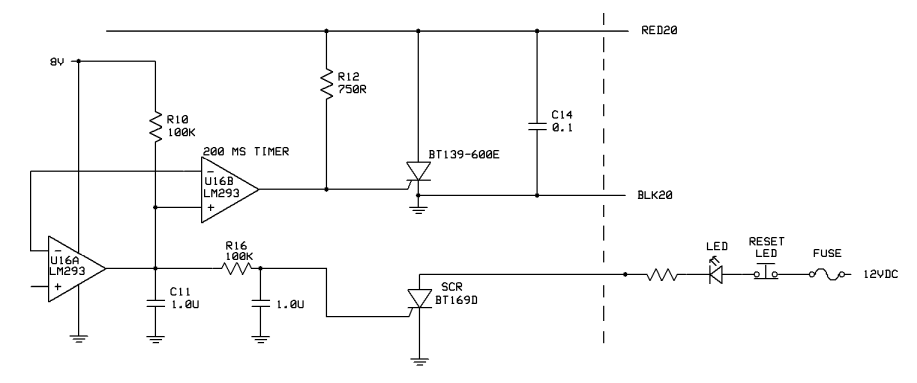
How about using a second SCR for an over-voltage tripped light?  Maybe

something like the attached circuit.  Keep in mind that I am not an electronic

engineer. I don't even play one of TV. 
| | - The Matronics AeroElectric-List Email Forum - | | | Use the List Feature Navigator to browse the many List utilities available such as the Email Subscriptions page, Archive Search & Download, 7-Day Browse, Chat, FAQ, Photoshare, and much more:
http://www.matronics.com/Navigator?AeroElectric-List |
|
| Description: |
|
| Filesize: |
29.56 KB |
| Viewed: |
51405 Time(s) |
|
_________________
Joe Gores
Last edited by user9253 on Tue Sep 26, 2023 5:31 pm; edited 1 time in total |
|
| Back to top |
|
|
Eric Page
Joined: 15 Feb 2017
Posts: 244
|
| Posted: Tue Sep 26, 2023 3:48 pm Post subject: Re: OVM14 MkIII, rev P1 |
|
|
| user9253 wrote: | | How about using a second SCR for an over-voltage tripped light? Maybe something like the attached circuit. |
See edits... 
| | - The Matronics AeroElectric-List Email Forum - | | | Use the List Feature Navigator to browse the many List utilities available such as the Email Subscriptions page, Archive Search & Download, 7-Day Browse, Chat, FAQ, Photoshare, and much more:
http://www.matronics.com/Navigator?AeroElectric-List |
|
| Description: |
|
| Filesize: |
35.5 KB |
| Viewed: |
51482 Time(s) |
|
|
|
| Back to top |
|
|
user9253
Joined: 28 Mar 2008
Posts: 1910
Location: Riley TWP Michigan
|
| Posted: Tue Sep 26, 2023 4:00 pm Post subject: Re: OVM14 MkIII, rev P1 |
|
|
I thought about that at first Eric, but it only takes 50 microamps to turn on the BT169D SCR.

I was concerned that much current would come via R12.
| | - The Matronics AeroElectric-List Email Forum - | | | Use the List Feature Navigator to browse the many List utilities available such as the Email Subscriptions page, Archive Search & Download, 7-Day Browse, Chat, FAQ, Photoshare, and much more:
http://www.matronics.com/Navigator?AeroElectric-List |
|
_________________
Joe Gores |
|
| Back to top |
|
|
user9253
Joined: 28 Mar 2008
Posts: 1910
Location: Riley TWP Michigan
|
| Posted: Tue Sep 26, 2023 5:37 pm Post subject: Re: OVM14 MkIII, rev P1 |
|
|
I fixed the LED polarity.  I kept the schematic simple by not drawing the test

circuit, but I think it is a good idea and should be included.
| | - The Matronics AeroElectric-List Email Forum - | | | Use the List Feature Navigator to browse the many List utilities available such as the Email Subscriptions page, Archive Search & Download, 7-Day Browse, Chat, FAQ, Photoshare, and much more:
http://www.matronics.com/Navigator?AeroElectric-List |
|
_________________
Joe Gores |
|
| Back to top |
|
|
user9253
Joined: 28 Mar 2008
Posts: 1910
Location: Riley TWP Michigan
|
| Posted: Wed Sep 27, 2023 1:51 pm Post subject: Re: OVM14 MkIII, rev P1 |
|
|
Eric, how about this circuit for an over-voltage indicator light?

I added a Schottky diode to prevent R12 current from turning on the BT169D SCR.
| | - The Matronics AeroElectric-List Email Forum - | | | Use the List Feature Navigator to browse the many List utilities available such as the Email Subscriptions page, Archive Search & Download, 7-Day Browse, Chat, FAQ, Photoshare, and much more:
http://www.matronics.com/Navigator?AeroElectric-List |
|
| Description: |
|
| Filesize: |
16.88 KB |
| Viewed: |
51426 Time(s) |
|
_________________
Joe Gores |
|
| Back to top |
|
|
Eric Page
Joined: 15 Feb 2017
Posts: 244
|
| Posted: Wed Sep 27, 2023 5:13 pm Post subject: Re: OVM14 MkIII, rev P1 |
|
|
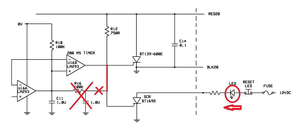
The output of the LM293 comparator is a bit strange.  It can "sink" current (draw current out of the circuit, to ground), but it can't "source" any current (supply current to the circuit).  It's a transistor that can either be on ("low," pulling anything connected to the output down to ground), or off ("high," doing nothing).  When the output is low (again, transistor on), the current that flows through resistor R12 is bled off to ground and can't do anything in the circuit.  When the output is high (transistor off), R12 can "pull up" the output node to the supply voltage and the current from R12 turns on the crowbar SCR.


The diode that you added will block the comparator's output transistor from being able to bleed R12 current out of the circuit, so the crowbar SCR will be permanently on.  Likewise, it will prevent any current from R12 from reaching the SCR in the LED circuit, so it will never turn on.  In this application, you can think of the diode as an electrical check valve; its symbol tells you which way current can flow (with the arrow).


To do what you want, the diode should be removed and both SCRs' gates should be connected to the node that's common to the comparator's output and the bottom of R12.  When the output goes high, current from R12 will turn on both SCRs, crowbarring the field breaker and turning on the LED.


Each SCR's gate will only absorb as much current as it needs to turn on.  Bob specified a 750-ohm resistor because the crowbar SCR is a high power device and it wants a stout gate current to trigger.  The SCR you selected for the LED requires so little current that it will trigger just fine from the same pull-up resistor as the bigger one.


-Eric
| | - The Matronics AeroElectric-List Email Forum - | | | Use the List Feature Navigator to browse the many List utilities available such as the Email Subscriptions page, Archive Search & Download, 7-Day Browse, Chat, FAQ, Photoshare, and much more:
http://www.matronics.com/Navigator?AeroElectric-List |
|
|
|
| Back to top |
|
|
|
|
You cannot post new topics in this forum
You cannot reply to topics in this forum
You cannot edit your posts in this forum
You cannot delete your posts in this forum
You cannot vote in polls in this forum
You cannot attach files in this forum
You can download files in this forum
|
Powered by phpBB © 2001, 2005 phpBB Group
|

