 |
Matronics Email Lists
Web Forum Interface to the Matronics Email Lists
|
| View previous topic :: View next topic |
| Author |
Message |
nuckolls.bob(at)aeroelect
Guest
|
 Posted: Mon Aug 14, 2023 4:29 pm Post subject: Next generation Crowbar OVM Posted: Mon Aug 14, 2023 4:29 pm Post subject: Next generation Crowbar OVM |
 |
|
| Quote: | | Looks promising. Do you have a schematic with part numbers? I'm not familiar with the zener diode symbol with a third pin (input) which appear to stabilize the 10V reference. |
That's an LM431 'adjustable zener' . . . a
big player in many of my contemporary projects.
I'm reluctant to publish values and part numbers
until the concept is, at least, bench tested
for conformance to design goals.
The motivation for publishing the 'cartoon' was
to plant seeds of an alternative idea based on
a couple decades of experience, allegiance to
the legacy design rules and just perhaps, a
bit of irritation at decisions driven more
by economics and bureaucratic intransigence
than a quest for the best we know how to
do.
The two ic's are lm311 style comparators.
You can probably dope out a workable
constellation of values based on the
stated design goals.
While the FET may indeed be suited to the
'crowbaring' of a circuit breaker, how
do we insure that it maintains a saturated,
on condition from the time it switches ON
until the breaker opens?
The gate voltage cannot fall below the minimum
value for necessary conduction while the
breaker is deciding to toss in the towel . . .
probably 15 to 50 milliseconds.
Thid critical performance question demands
more prayer over the drawing board.
Thank you so much for your interest . . .
Bob . . .
////
(o o)
===========o00o=(_)=o00o=========
< Go ahead, make my day . . . >
< show me where I'm wrong. >
=================================
In the interest of creative evolution
of the-best-we-know-how-to-do based
on physics and good practice.
| | - The Matronics AeroElectric-List Email Forum - | | | Use the List Feature Navigator to browse the many List utilities available such as the Email Subscriptions page, Archive Search & Download, 7-Day Browse, Chat, FAQ, Photoshare, and much more:
http://www.matronics.com/Navigator?AeroElectric-List |
|
|
|
| Back to top |
|
 |
Eric Page
Joined: 15 Feb 2017
Posts: 244
|
| Posted: Mon Aug 14, 2023 9:11 pm Post subject: Re: Next generation Crowbar OVM |
|
|
Thanks for including all of the history on your OVP efforts in your first reply, Bob. It's fascinating to hear how these things developed over time, and to see how the regulatory and corporate bureaucracies stand in the way of progress.
Quoting from your replies in my thread and this one, in no particular order...
| Quote: | | DO-160/Mil-STD-704 dictates even back then called for a certifiable appliance to withstand a 20V excursion for 1 Second; a 40V excursion for 100 milliseconds. |
So, if I understand this correctly, and read between the lines a little bit, the ~3mS delay in your legacy OVP circuit...
http://www.aeroelectric.com/DIY/DIY_Crowbar_OVP_F.pdf
...is shorter than ideal, and the relevant standards allow a much longer response time. If we adopt a longer delay, we get a system that's significantly more tolerant of bus transients but still protects our avionics when things truly go sideways. Does that sound right?
| Quote: | While the FET may indeed be suited to the 'crowbarring' of a circuit breaker, how do we insure that it maintains a saturated, on condition from the time it switches ON until the breaker opens?
The gate voltage cannot fall below the minimum value for necessary conduction while the breaker is deciding to toss in the towel... probably 15 to 50 milliseconds. |
Yeah, good point. When the FET turns on, the supply is pulled HARD toward 0V, which kills the FET's gate drive.
Perhaps the following might work (see "Crowbar FET.pdf" below): Isolate the pullup resistor from the rest of the 10V circuit using a diode with low reverse leakage (i.e. BAS33: 1nA(at)15V), use a modestly low value pullup resistor (1k?) and a logic-level FET so the minimum Rds-on occurs at a low drive voltage.
Something like the IRLZ44 (TO-220 through-hole) or BUK962 (TO-263-3 surface mount) might work. Both are limited to a Vgs of +/-10V, but that's protected by the forward voltage of the isolating diode. I couldn't find any high current, logic level FETs with higher Vgs.
FET datasheets:
IRLZ44: https://www.vishay.com/docs/91328/irlz44.pdf
BUK962: https://assets.nexperia.com/documents/data-sheet/BUK962R5-60E.pdf
| Quote: | | You can probably dope out a workable constellation of values based on the stated design goals. |
Indeed, I took a stab at it with an eye toward using it as a relay driver for a PM stator (see "2-Comp OVP Relay Driver.pdf" below).
- Used an LM393 (vs the LM311, the LM393 has two comparators in one package and it's cheaper).
- P-FET on the output to drive relay coil(s).
- N-FET to latch timer comparator's reference input to ground.
- Separate reference divider for timer comparator so latching FET can't pull 431's REF pin to ground.
- 7.5V Zener on both comparators to protect non-inverting inputs from exceeding Vsupply minus 2V (LM393's input voltage range).
- N-FET to ensure timing capacitor is fully discharged during reset so comparator can't restart in latched state.
- Timing: 10V charging 10uF through 10k should take ~69mS to reach the 5V reference.
What do you think? Is a 69mS delay OK, or would you aim for something shorter or longer?
-Eric
| | - The Matronics AeroElectric-List Email Forum - | | | Use the List Feature Navigator to browse the many List utilities available such as the Email Subscriptions page, Archive Search & Download, 7-Day Browse, Chat, FAQ, Photoshare, and much more:
http://www.matronics.com/Navigator?AeroElectric-List |
|
| Description: |
|

Download |
| Filename: |
Crowbar FET.pdf |
| Filesize: |
7.7 KB |
| Downloaded: |
53 Time(s) |
| Description: |
|
Download |
| Filename: |
2-Comp OVP Relay Driver.pdf |
| Filesize: |
21.97 KB |
| Downloaded: |
51 Time(s) |
|
|
| Back to top |
|
|
finn.lassen(at)verizon.ne
Guest
|
| Posted: Tue Aug 15, 2023 12:49 pm Post subject: Next generation Crowbar OVM |
|
|
On 8/14/2023 8:28 PM, Robert L. Nuckolls, III wrote:
| Quote: | | Quote: | | Looks promising. Do you have a schematic with part numbers? I'm not familiar with the zener diode symbol with a third pin (input) which appear to stabilize the 10V reference. |
� That's an LM431 'adjustable zener' . . . a
� big player in many of my contemporary projects.
� I'm reluctant to publish values and part numbers
� until the concept is, at least, bench tested
� for conformance to design goals.
� The motivation for publishing the 'cartoon' was
� to plant seeds of an alternative idea based on
� a couple decades of experience, allegiance to
� the legacy design rules and just perhaps, a
� bit of irritation at decisions driven more
� by economics and bureaucratic intransigence
� than a quest for the best we know how to
� do.
� The two ic's are lm311 style comparators.
� You can probably dope out a workable
� constellation of values based on the
� stated design goals.
� While the FET may indeed be suited to the
� 'crowbaring' of a circuit breaker, how
� do we insure that it maintains a saturated,
� on condition from the time it switches ON
� until the breaker opens?
� The gate voltage cannot fall below the minimum
� value for necessary conduction while the
� breaker is deciding to toss in the towel . . .
� probably 15 to 50 milliseconds.
� Thid critical performance question demands
� more prayer over the drawing board.
� Thank you so much for your interest . . .
� Bob . . .
.
|
Thanks Bob, that's a handy device if one doesn't happen to have a zener on hand with desired voltage, even if it doee require two resistors.
I'd forgotten that LM311's can have open collector outputs (when tying output transistor emitter to ground). Still have several in my old parts bins but more than four decades since last used one.
I'm thinking the SCR is still the better choice for a crowbar circuit. But if we're changing the OVP circuit to a relay disconnect between alternator and battery/bus a FET or other device that can drive the relay may be OK. Assuming the OVP monitors alternator voltage and not bus voltage.
Finn
| | - The Matronics AeroElectric-List Email Forum - | | | Use the List Feature Navigator to browse the many List utilities available such as the Email Subscriptions page, Archive Search & Download, 7-Day Browse, Chat, FAQ, Photoshare, and much more:
http://www.matronics.com/Navigator?AeroElectric-List |
|
|
|
| Back to top |
|
|
nuckolls.bob(at)aeroelect
Guest
|
| Posted: Tue Aug 15, 2023 4:16 pm Post subject: Next generation Crowbar OVM |
|
|
Good eye my friend! That's a typo. Just to be sure, I ran the
traps on circuit values and came up with approx 60mS to trip
for a more realistic rate of rise for a faulted alternator
driving a flightworthy battery. Still pretty fast having
sorta caved to legacy certified designs. Gonna quit that
and go for any event exceeding 16.0+/-0.5Volts AND 500+/-0.50Seconds; well
inside design goals cited by DO160/MIL-Std-704.
I'll go fix that posting . . . or maybe just take
it down. The very first CBOVM-14s I delivered
exploited a relatively precise 10.V trigger
diode that were 'calibrated' as-assembled.
First the diode went obsolete and now attractive
SCRs are more difficult to find. Time for the
BROAD BRUSH upgrade.
| Quote: | ...is shorter than ideal, and the relevant standards allow a much longer response time. If we adopt a longer delay, we get a system that's significantly more tolerant of bus transients but still protects our avionics when things truly go sideways. Does that sound right?
> While the FET may indeed be suited to the 'crowbarring' of a circuit breaker, how do we insure that it maintains a saturated, on condition from the time it switches ON until the breaker opens?
>
> The gate voltage cannot fall below the minimum value for necessary conduction while the breaker is deciding to toss in the towel... probably 15 to 50 milliseconds.
Yeah, good point. When the FET turns on, the supply is pulled HARD toward 0V, which kills the FET's gate drive. |
Also good eye. Vcc for the electronics will need to be
diode isolated from the effects of the crowbar pull down.
The capacitor across Vcc will be large enough to hold
the crowbar action ACTIVE long enough to trip the breaker.
I'll have to check again but I think the circuit demands on
Vcc will be on the order of 1mA. Keeping Vcc at or above
5v for 200mS or so shouldn't be hard.
| Quote: | Perhaps the following might work (see "Crowbar FET.pdf" below): Isolate the pullup resistor from the rest of the 10V circuit using a diode with low reverse leakage (i.e. BAS33: 1nA(at)15V), use a modestly low value pullup resistor (1k?) and a logic-level FET so the minimum Rds-on occurs at a low drive voltage.
Something like the IRLZ44 (TO-220 through-hole) or BUK962 (TO-263-3 surface mount) might work. Both are limited to a Vgs of +/-10V, but that's protected by the forward voltage of the isolating diode. I couldn't find any high current, logic level FETs with higher Vgs.
FET datasheets:
IRLZ44: https://www.vishay.com/docs/91328/irlz44.pdf
BUK962: https://assets.nexperia.com/documents/data-sheet/BUK962R5-60E.pdf
> You can probably dope out a workable constellation of values based on the stated design goals.
Indeed, I took a stab at it with an eye toward using it as a relay driver for a PM stator (see "2-Comp OVP Relay Driver.pdf" below).
- Used an LM393 (vs the LM311, the LM393 has two comparators in one package and it's cheaper).
- P-FET on the output to drive relay coil(s).
- N-FET to latch timer comparator's reference input to ground.
- Separate reference divider for timer comparator so latching FET can't pull 431's REF pin to ground.
- 7.5V Zener on both comparators to protect non-inverting inputs from exceeding Vsupply minus 2V (LM393's input voltage range).
- N-FET to ensure timing capacitor is fully discharged during reset so comparator can't restart in latched state.
- Timing: 10V charging 10uF through 10k should take ~69mS to reach the 5V reference.
What do you think? Is a 69mS delay OK, or would you aim for something shorter or longer? |
I'd go for the whole 500 MSec enchilada.
Yeah, need to resolve the issues with trip
dynamics to make sure the FET stays on
for at least 200mS to open the breaker.
I've toyed with the notion of a 3-wire
configuration where Vcc is derived from
say the battery bus (A draw of about 1mA
. . . insignificant) leaving only the
crowbar breaker on the main bus.
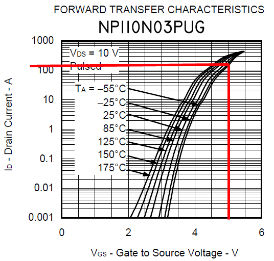
At the moment, I'm rather enamored of the
NEC NP110N03PUG FET. This little guy will
grunt over 200A at low temperatures with
a Vgs of only 5V.
Let's continue to continue . . .
Bob . . .
////
(o o)
===========o00o=(_)=o00o=========
< Go ahead, make my day . . . >
< show me where I'm wrong. >
=================================
In the interest of creative evolution
of the-best-we-know-how-to-do based
on physics and good practice.
| | - The Matronics AeroElectric-List Email Forum - | | | Use the List Feature Navigator to browse the many List utilities available such as the Email Subscriptions page, Archive Search & Download, 7-Day Browse, Chat, FAQ, Photoshare, and much more:
http://www.matronics.com/Navigator?AeroElectric-List |
|
| Description: |
|
| Filesize: |
200.11 KB |
| Viewed: |
919 Time(s) |
|
|
|
| Back to top |
|
|
Eric Page
Joined: 15 Feb 2017
Posts: 244
|
| Posted: Wed Aug 16, 2023 8:05 am Post subject: Re: Next generation Crowbar OVM |
|
|
| nuckolls.bob(at)aeroelect wrote: | ...go for any event exceeding 16.0+/-0.5Volts AND 500+/-0.50Seconds; well inside design goals cited by DO160/MIL-Std-704.
[...]
I'd go for the whole 500 MSec enchilada. |
Copy all; thanks. I'll update my schematic accordingly. Hitting that target will be a lot easier than it was to hit exactly 3mS!
| Quote: | | At the moment, I'm rather enamored of the NEC NP110N03PUG FET. This little guy will grunt over 200A at low temperatures with a Vgs of only 5V. |
Looks good, but... does the 30V max Vds present a risk of avalanche breakdown during a short-duration (i.e. not long enough to trip the timer) OV transient? The BUK962 that I mentioned above has a max Vds of 60V and the transfer characteristic chart looks even better.
But... depending upon what the crowbar pulse looks like, it might fall outside the bounds of the Safe Operating Area chart for either of those FETs.
What is it that this task demands that isn't met by an available SCR?
| | - The Matronics AeroElectric-List Email Forum - | | | Use the List Feature Navigator to browse the many List utilities available such as the Email Subscriptions page, Archive Search & Download, 7-Day Browse, Chat, FAQ, Photoshare, and much more:
http://www.matronics.com/Navigator?AeroElectric-List |
|
|
|
| Back to top |
|
|
nuckolls.bob(at)aeroelect
Guest
|
| Posted: Wed Aug 16, 2023 2:06 pm Post subject: Next generation Crowbar OVM |
|
|
| Quote: | Thanks Bob, that's a handy device if one doesn't happen to have a zener on hand with desired voltage, even if it doee require two resistors.
I'd forgotten that LM311's can have open collector outputs (when tying output transistor emitter to ground). Still have several in my old parts bins but more than four decades since last used one.
I'm thinking the SCR is still the better choice for a crowbar circuit. But if we're changing the OVP circuit to a relay disconnect between alternator and battery/bus a FET or other device that can drive the relay may be OK. Assuming the OVP monitors alternator voltage and not bus voltage. |
Those two voltages are generally the same as
long as we're talking about the main bus.
Yeah, the SCR configuration has some really
desirable features, namely it's an AC device
that inherently 'latches' in DC service. Don't
need to worry about gate drive latency.
So for the moment, I'm trying to stuff a more
modern NFET into that slot. But if I could find
a suitable SCR not likely to disappear in the
next few years . . . yeah, let us lament the
evolution of selenium rectifiers.
The 'crowbar' approach that opens the control
power source yields a kind of universal configuration
in the spirit and intent of the original CBOVM-14
products. Yet it may well be that 'progress'
in component evolution makes that a
goal-too-far.
Good input sir!
Bob . . .
////
(o o)
===========o00o=(_)=o00o=========
< Go ahead, make my day . . . >
< show me where I'm wrong. >
=================================
In the interest of creative evolution
of the-best-we-know-how-to-do based
on physics and good practice.
| | - The Matronics AeroElectric-List Email Forum - | | | Use the List Feature Navigator to browse the many List utilities available such as the Email Subscriptions page, Archive Search & Download, 7-Day Browse, Chat, FAQ, Photoshare, and much more:
http://www.matronics.com/Navigator?AeroElectric-List |
|
|
|
| Back to top |
|
|
nuckolls.bob(at)aeroelect
Guest
|
| Posted: Thu Aug 17, 2023 11:12 am Post subject: Next generation Crowbar OVM |
|
|
| Quote: | | Quote: | | Thanks Bob, that's a handy device if one doesn't happen to have a zener on hand with desired voltage, even if it doee require two resistors. |
|
best yet, they're really cheap and
0.5% tolerance. Vcc is generally
tight enough to serve both as power
and reference.
Bob . . .
////
(o o)
===========o00o=(_)=o00o=========
< Go ahead, make my day . . . >
< show me where I'm wrong. >
=================================
In the interest of creative evolution
of the-best-we-know-how-to-do based
on physics and good practice.
| | - The Matronics AeroElectric-List Email Forum - | | | Use the List Feature Navigator to browse the many List utilities available such as the Email Subscriptions page, Archive Search & Download, 7-Day Browse, Chat, FAQ, Photoshare, and much more:
http://www.matronics.com/Navigator?AeroElectric-List |
|
|
|
| Back to top |
|
|
nuckolls.bob(at)aeroelect
Guest
|
| Posted: Thu Aug 24, 2023 1:10 pm Post subject: Next generation Crowbar OVM |
|
|
| Quote: | | Quote: | > While the FET may indeed be suited to the 'crowbarring' of a circuit breaker, how do we insure that it maintains a saturated, on condition from the time it switches ON until the breaker opens?
>
> The gate voltage cannot fall below the minimum value for necessary conduction while the breaker is deciding to toss in the towel... probably 15 to 50 milliseconds.
Yeah, good point. When the FET turns on, the supply is pulled HARD toward 0V, which kills the FET's gate drive. |
Also good eye. Vcc for the electronics will need to be
diode isolated from the effects of the crowbar pull down.
The capacitor across Vcc will be large enough to hold
the crowbar action ACTIVE long enough to trip the breaker. |
Your comment prompted further inquiry into suitable
replacements for the SCR I had been using. Don't
know what I entered 'wrong' in the search parameters
but another look produced this little gem:
https://www.ween-semi.com/sites/default/files/2022-02/TYN30-600TF.pdf
Very sensitive gate current (10 mA). Specifically
cited for 'crowbar service'. Price is right too.
I've got some on order.
This illustrates the value of collaborative dialog.
I might well have peddled down the FET pathway
with success as yet to be demonstrated. Your
comment prompted another look into the 'devil-
we-know' technology with what appears to be
a superior solution that's more compatible with
the very low-power, comparator-timer configuration.
Don't know how I missed it the first time at-bat.
I'm headed out with the grandma and grandson for
Oregon to get my little brother married off . . .
and to let grandson stick his toes in the Pacific.
We'll be pretty much out of pocket until Sept 6
although I can peek in from time to time through
the web browser portal.
In the mean time, I'll have plenty of opportunity
to conduct some asphalt engineering. I'll knock
out an ECB to see how well we can make this
fourth generation CBOVM sing, dance and do
dishes.
Thanks for your input!
Bob . . .
////
(o o)
===========o00o=(_)=o00o=========
< Go ahead, make my day . . . >
< show me where I'm wrong. >
=================================
In the interest of creative evolution
of the-best-we-know-how-to-do based
on physics and good practice.
| | - The Matronics AeroElectric-List Email Forum - | | | Use the List Feature Navigator to browse the many List utilities available such as the Email Subscriptions page, Archive Search & Download, 7-Day Browse, Chat, FAQ, Photoshare, and much more:
http://www.matronics.com/Navigator?AeroElectric-List |
|
|
|
| Back to top |
|
|
finn.lassen(at)verizon.ne
Guest
|
| Posted: Thu Aug 24, 2023 1:43 pm Post subject: Next generation Crowbar OVM |
|
|
On 8/24/2023 5:10 PM, Robert L. Nuckolls, III wrote:
| Quote: | | Quote: | | Quote: | > While the FET may indeed be suited to the 'crowbarring' of a circuit breaker, how do we insure that it maintains a saturated, on condition from the time it switches ON until the breaker opens?
>
> The gate voltage cannot fall below the minimum value for necessary conduction while the breaker is deciding to toss in the towel... probably 15 to 50 milliseconds.
Yeah, good point.� When the FET turns on, the supply is pulled HARD toward 0V, which kills the FET's gate drive. |
�� Also good eye. Vcc for the electronics will need to be
�� diode isolated from the effects of the crowbar pull down.
�� The capacitor across Vcc will be large enough to hold
�� the crowbar action ACTIVE long enough to trip the breaker. |
� Your comment prompted further inquiry into suitable
� replacements for the SCR I had been using. Don't
� know what I entered 'wrong' in the search parameters
� but another look produced this little gem:
https://www.ween-semi.com/sites/default/files/2022-02/TYN30-600TF.pdf
� Very sensitive gate current (10 mA). Specifically
� cited for 'crowbar service'. Price is right too.
� I've got some on order.
� This illustrates the value of collaborative dialog.
� I might well have peddled down the FET pathway
� with success as yet to be demonstrated. Your
� comment prompted another look into the 'devil-
� we-know' technology with what appears to be
� a superior solution that's more compatible with
� the very low-power, comparator-timer configuration.
� Don't know how I missed it the first time at-bat.
� I'm headed out with the grandma and grandson for
� Oregon to get my little brother married off . . .
� and to let grandson stick his toes in the Pacific.
� We'll be pretty much out of pocket until Sept 6
� although I can peek in from time to time through
� the web browser portal.
� In the mean time, I'll have plenty of opportunity
� to conduct some asphalt engineering.� I'll knock
� out an ECB to see how well we can make this
� fourth generation CBOVM sing, dance and do
� dishes.
� Thanks for your input!
� Bob . . .
|
I just ordered a couple of these:from DigiKey:
 SCT640B SCT640B
1655-2116-ND
SCR 600V 40A TO220B
$2.27 each, more than twice the TYN30-600TF 
The TYN30-600TF has a lower trigger voltage (1V) compared to the SCT640B (1.5V) but 35mA gate current but same as the S4025 (1.55V and 35mA) we're trying to replace.
BTW, I was able to order the MBS4991 on eBay, so still possible to make the original OVP in small quantities.
Finn
| | - The Matronics AeroElectric-List Email Forum - | | | Use the List Feature Navigator to browse the many List utilities available such as the Email Subscriptions page, Archive Search & Download, 7-Day Browse, Chat, FAQ, Photoshare, and much more:
http://www.matronics.com/Navigator?AeroElectric-List |
|
|
|
| Back to top |
|
|
nuckolls.bob(at)aeroelect
Guest
|
| Posted: Thu Aug 24, 2023 3:42 pm Post subject: Next generation Crowbar OVM |
|
|
| Quote: |
1655-2116-ND
SCR 600V 40A TO220B
$2.27 each, more than twice the TYN30-600TF
The TYN30-600TF has a lower trigger voltage (1V) compared to the SCT640B (1.5V) but 35mA gate current but same as the S4025 (1.55V and 35mA) we're trying to replace.
BTW, I was able to order the MBS4991 on eBay, so still possible to make the original OVP in small quantities.
Finn |
Let us know how your experiment works out!
Bob . . .
////
(o o)
===========o00o=(_)=o00o=========
< Go ahead, make my day . . . >
< show me where I'm wrong. >
=================================
In the interest of creative evolution
of the-best-we-know-how-to-do based
on physics and good practice.
| | - The Matronics AeroElectric-List Email Forum - | | | Use the List Feature Navigator to browse the many List utilities available such as the Email Subscriptions page, Archive Search & Download, 7-Day Browse, Chat, FAQ, Photoshare, and much more:
http://www.matronics.com/Navigator?AeroElectric-List |
|
|
|
| Back to top |
|
|
|
|
You cannot post new topics in this forum
You cannot reply to topics in this forum
You cannot edit your posts in this forum
You cannot delete your posts in this forum
You cannot vote in polls in this forum
You cannot attach files in this forum
You can download files in this forum
|
Powered by phpBB © 2001, 2005 phpBB Group
|

