 |
Matronics Email Lists
Web Forum Interface to the Matronics Email Lists
|
| View previous topic :: View next topic |
| Author |
Message |
velletazjp
Joined: 08 Oct 2019
Posts: 11
|
 Posted: Wed Apr 01, 2026 12:37 am Post subject: Z12 Review for my Experimental Robin DR250 Posted: Wed Apr 01, 2026 12:37 am Post subject: Z12 Review for my Experimental Robin DR250 |
 |
|
Hello all,
I would greatly appreciate a review of my electrical wiring diagram, and I would be especially grateful for any feedback.
This is a 4-seat, wood & fabric, amateur-built, tailwheel aircraft. It's a clone of the famous Robin DR250.
The primary mission is day VFR, with a strong focus on mountain flying. The aircraft will also be used for cross-country flights, with occasional night VFR and light IFR operations (no icing - no precipitations) (supported by a certified GPS).
The engine is a Lycoming IO-360 (parallel valve) equipped with a Bendix-style mechanical fuel injection system. Ignition is currently provided by dual Slick magnetos, with provisions for a future upgrade to an electronic ignition system (PMAG).
The electrical generation system consists of:
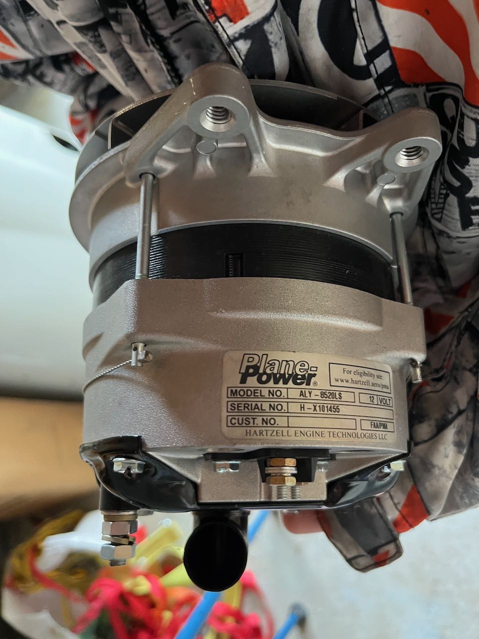
- A PlanePower alternator (12V, 60A – ALY-8520LS) regulated by a B&C LR3E
- Backup alternator: B&C 410H with LS1B standby regulator
The avionics suite is based on Garmin G3X, including:
GAD27, GEA24
Dual-screen setup (PFD + MFD)
2-axis autopilot (GSA 28 servos)
The aircraft is equipped with:
Electric roll trim (Ray Allen T3-12A)
Electric pitch trim (Thomson Linear MD12)
Both trims are controlled through the Garmin autopilot servos.
The electrical distribution is organized around three buses:
MAIN BUS (20 positions)
E-BUS (10 positions)
BATT BUS (6 positions)
All using fuse blocks.
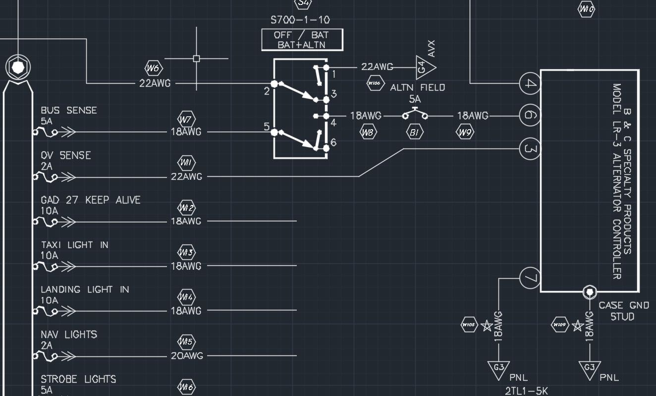
The architecture is based on the Z12 (dual alternator, single battery) design, with minimal modifications:
Replacement of fuselinks with ANL current limiters, as seen in more recent architectures
Replacement of shunt fuselinks with 1A breakers, per Garmin G3X installation manual recommendations
I am also intentionally trying to keep the number of circuit breakers to a strict minimum. At this stage, only two breakers are used, both dedicated to alternator field activation.
You will find the wiring diagram below.
Any comments, critiques, or suggestions are more than welcome.
Thank you very much for your time and expertise.
Best regards,
JP
| | - The Matronics AeroElectric-List Email Forum - | | | Use the List Feature Navigator to browse the many List utilities available such as the Email Subscriptions page, Archive Search & Download, 7-Day Browse, Chat, FAQ, Photoshare, and much more:
http://www.matronics.com/Navigator?AeroElectric-List |
|
| Description: |
|

Download |
| Filename: |
DH 251 panel G3X.pdf |
| Filesize: |
81.01 KB |
| Downloaded: |
185 Time(s) |
| Description: |
|
Download |
| Filename: |
F-PEZZ G3x avionique Interconex wiring schematics.pdf |
| Filesize: |
72.78 KB |
| Downloaded: |
172 Time(s) |
| Description: |
|
Download |
| Filename: |
F-PEZZ electrical diagram dual Alternators single battery (Z12) G3x integration.pdf |
| Filesize: |
166.87 KB |
| Downloaded: |
183 Time(s) |
| Description: |
|
Download |
| Filename: |
e-bus load analysis.pdf |
| Filesize: |
55.45 KB |
| Downloaded: |
180 Time(s) |
_________________
2020 contribution paid |
|
| Back to top |
|
 |
user9253
Joined: 28 Mar 2008
Posts: 1975
Location: Riley TWP Michigan
|
| Posted: Sat Apr 04, 2026 1:21 pm Post subject: Re: Z12 Review for my Experimental Robin DR250 |
|
|
Using one of Bob Nuckolls' diagrams with minimal modifications is a good way to go.  You might consider using hall effect sensors instead of shunts.

Amploc has issued an END OF LIFE announcement for their KEY100 Hall Effect Sensor (and several others) effective June 1, 2026.
| | - The Matronics AeroElectric-List Email Forum - | | | Use the List Feature Navigator to browse the many List utilities available such as the Email Subscriptions page, Archive Search & Download, 7-Day Browse, Chat, FAQ, Photoshare, and much more:
http://www.matronics.com/Navigator?AeroElectric-List |
|
_________________
Joe Gores |
|
| Back to top |
|
|
wsimpso1
Joined: 04 Nov 2018
Posts: 40
Location: Saline MI
|
| Posted: Fri Apr 10, 2026 5:49 am Post subject: Re: Z12 Review for my Experimental Robin DR250 |
|
|
Using Z-12 is a great base.


I question having most of your Garmin suite on th essential bus. When do you need to turn off the main bus? Smoke in the cockpit is a big one. You don't 't know which wire orbox is smoking, so you kill the whole main bus. The more things you put on the Essential Bus, the more likely you are to not shut off the smoking stuff...  We usually only want REALLY  Essential stuff on the Essential Bus.


Then, after your smoking elements have gone to sleep, if you need something on the main bus, you can shut off everything on the main bus, turn on the Master, smell for smoke, try that item you need, smell for smoke, and get on the ground.


Now comes the nightmare. The smoke was being let out of something you really need. From my quick review, you have two EFIS, so gyro and altimetry functions are still available even if one EFIS is down, but you only have one GPS/NAV/COM. Good reason to have fully charged and engaged EFB and know how to engage it's backup display and Nav functions....


Billski
| | - The Matronics AeroElectric-List Email Forum - | | | Use the List Feature Navigator to browse the many List utilities available such as the Email Subscriptions page, Archive Search & Download, 7-Day Browse, Chat, FAQ, Photoshare, and much more:
http://www.matronics.com/Navigator?AeroElectric-List |
|
|
|
| Back to top |
|
|
velletazjp
Joined: 08 Oct 2019
Posts: 11
|
| Posted: Mon Apr 13, 2026 7:31 am Post subject: Re: Z12 Review for my Experimental Robin DR250 |
|
|
Thank you all for the very useful feedback.
I have updated the wiring accordingly and I am trying to stay as close as possible to Bob Nuckolls’ Z-12 philosophy.
My design intent for the endurance bus is the following:
in normal operation, all equipment is powered from the main bus
in case of loss of the main alternator, I want to be able to continue the flight on the endurance bus with the standby alternator
in case I need to shed the main bus, I want the endurance bus to keep only the truly necessary loads for safe continuation and landing
So I understand the concern about having too much Garmin equipment on the endurance bus, especially in a smoke-in-cockpit scenario. That is a very fair point. My goal is not to make the E-Bus a “second main bus”, but to preserve the minimum capability needed to keep control, navigate, communicate, and get on the ground.
Regarding the suggestion to use Hall effect sensors instead of shunts, I may have misunderstood the intent of that comment. My hesitation is that the AMPLOC KEY100 have an official end-of-life notice with no recommended replacement listed by the manufacturer. Since the G3X can also work with a conventional shunt, I am not sure a Hall sensor is the best path for a new installation at this point.
I also have a regulator/alternator integration question:
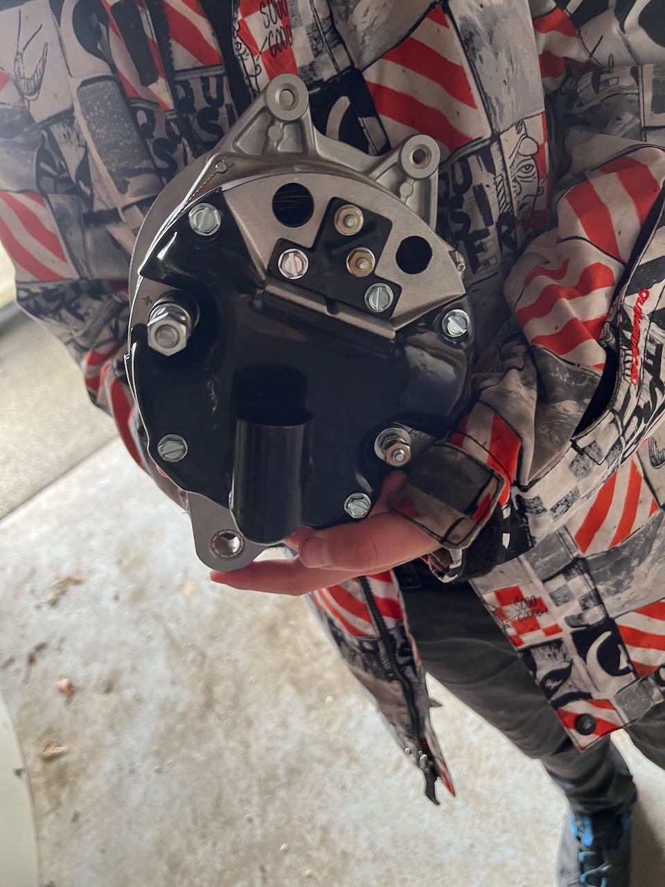
My main alternator is a Plane Power ALY-8520LS, and I plan to use a B&C LR3E regulator.
From what I understand:
the LR3 field output should go to the alternator F1 lead
F2 on some Plane Power/Hartzell units is either internally grounded or intended to be grounded externally, depending on configuration
I do not see a clear need for the AUX terminal when using the LR3E as a basic external regulator
Am I understanding this correctly?
More specifically:
Is the Plane Power ALY-8520LS considered fully compatible with the B&C LR3E?
Should I connect only F1 to the LR3E field output?
Should F2 be grounded, or is it already internally grounded on this alternator?
Should the AUX terminal remain unused in this installation?
My objective is to keep the architecture simple, robust, and as faithful as practical to the Z-12 concept, while still matching the Garmin/G3X installation requirements.
Thank you again for your time and for reviewing the updated diagram.
| | - The Matronics AeroElectric-List Email Forum - | | | Use the List Feature Navigator to browse the many List utilities available such as the Email Subscriptions page, Archive Search & Download, 7-Day Browse, Chat, FAQ, Photoshare, and much more:
http://www.matronics.com/Navigator?AeroElectric-List |
|
| Description: |
|
| Filesize: |
112.59 KB |
| Viewed: |
755236 Time(s) |
|
| Description: |
|
| Filesize: |
397.99 KB |
| Viewed: |
755236 Time(s) |
|
| Description: |
|
| Filesize: |
388.96 KB |
| Viewed: |
755236 Time(s) |
|
| Description: |
|
Download |
| Filename: |
F-PEZZ electrical diagram dual Alternators single battery (Z12) G3x integration-Model-2.pdf |
| Filesize: |
241.91 KB |
| Downloaded: |
151 Time(s) |
_________________
2020 contribution paid |
|
| Back to top |
|
|
user9253
Joined: 28 Mar 2008
Posts: 1975
Location: Riley TWP Michigan
|
|
| Back to top |
|
|
velletazjp
Joined: 08 Oct 2019
Posts: 11
|
| Posted: Wed May 13, 2026 12:09 am Post subject: Re: Z12 Review for my Experimental Robin DR250 |
|
|
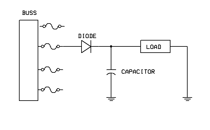
I have a specific question about the design:


There is no capacitor in the Z-12 design. Should I add one? If so, where should it be installed — after the alternator on the B-lead, or at the main bus connection? And should there also be a second one at the E-BUS connection?


Thanks!
| | - The Matronics AeroElectric-List Email Forum - | | | Use the List Feature Navigator to browse the many List utilities available such as the Email Subscriptions page, Archive Search & Download, 7-Day Browse, Chat, FAQ, Photoshare, and much more:
http://www.matronics.com/Navigator?AeroElectric-List |
|
_________________
2020 contribution paid |
|
| Back to top |
|
|
user9253
Joined: 28 Mar 2008
Posts: 1975
Location: Riley TWP Michigan
|
| Posted: Wed May 13, 2026 8:30 am Post subject: Re: Z12 Review for my Experimental Robin DR250 |
|
|
My opinion:

Most avionics are designed to live with a noisy aircraft electrical system.

Any capacitor capable of eliminating electrical noise from an aircraft electrical system would be too big and too heavy and too expensive.

If you desire to install a capacitor to reduce electrical noise on the supply to an individual load, I suggest isolating it with a diode.


Read this https://www.rotax-owner.com/en/912-914-technical-questions/7754-capacitors

Bob Nuckolls wrote: "Short answer is I don't think the capacitor adds any useful benefit."
| | - The Matronics AeroElectric-List Email Forum - | | | Use the List Feature Navigator to browse the many List utilities available such as the Email Subscriptions page, Archive Search & Download, 7-Day Browse, Chat, FAQ, Photoshare, and much more:
http://www.matronics.com/Navigator?AeroElectric-List |
|
| Description: |
|
| Filesize: |
1.25 KB |
| Viewed: |
748283 Time(s) |
|
_________________
Joe Gores |
|
| Back to top |
|
|
Eric Page
Joined: 15 Feb 2017
Posts: 278
|
| Posted: Wed May 13, 2026 8:43 am Post subject: Re: Z12 Review for my Experimental Robin DR250 |
|
|
Some regulators like to see a capacitor and some work fine without it.  For example, Rotax requires a 22,000μF cap near their regulators, but the installation document for the B&C LR3C...


https://bandc.com/wp-content/uploads/2018/05/lr3c_dgm_rev4-01.pdf


...doesn't seem to require one.  A quick email to B&C (sales(at)bandc.com) would get you a definitive answer.  They've been responsive each time I've emailed them with a question.
| | - The Matronics AeroElectric-List Email Forum - | | | Use the List Feature Navigator to browse the many List utilities available such as the Email Subscriptions page, Archive Search & Download, 7-Day Browse, Chat, FAQ, Photoshare, and much more:
http://www.matronics.com/Navigator?AeroElectric-List |
|
|
|
| Back to top |
|
|
johnbright

Joined: 14 Dec 2011
Posts: 167
Location: Newport News, VA
|
| Posted: Thu May 14, 2026 2:55 pm Post subject: Re: Z12 Review for my Experimental Robin DR250 |
|
|
Dear OP velletazjp,


My thoughts...


Why not use Z101 which AFAIK is intended to obsolete Z12. Z101 puts the aux alternator B lead on the battery, this way in case of smoke-in-the-cockpit-main-master-off the main bus is down and the e bus still has an alternator.


Are you aware of Monkworkz 30A PM vacuum pad generator? Starts and runs with no battery present. Delivers 30A at 1800 Lycoming RPM. Its B lead could be connected to the e bus, can't go on the battery due to parasitic load.


There's a later rev N of Z12 versus the rev M you started with. I don't know the differences.


Suggest you label your schematics with rev number and date. It's also valuable to show where the firewall is, and the baggage bulkhead in case of rear battery.


Bob Nuckolls recommends using LR3 for backup alternator. BTW SB-1 will flash the lamp over 20A even though the alternator is capable of more at cruise RPM. Lamp is an "idiot light"... better to look for voltage sag.


AFAIK Z template schematics have been moving to fuselinks for alternator B leads since about 2020.

I personally use a 100A MIDI fuse on a 60A alternator and a 50A MIDI fuse on a vacuum pad alternator.

B&C 410-H puts out 32A at 2700 Lycoming RPM.


Re shunt sense wires: IMO shop made 24 awg fuselinks connected to 20 awg feeders to the electronic box are easier / more compact / more reliable vs fuses. Ref Bob Nuckolls' fabrication instructions.

Note COTS fuselink wire smallest available in small quantity is 20 awg.


The alternator field feeder between the bus and the 5A breaker is protected by FLW because a fuse will open before the breaker does and the crew resettable breaker is needed in case of "nuisance" trip.

Newer Z schematics show 20 awg FLW to 16 awg feeder; this is for COTS 20 awg FLW. Older Z schematics showed 22 awg FLW to 18 awg feeder; this is for 22 awg shop made fuselinks.


Your "... -Model-2.pdf" schematic erroneously labels the master switch as 1-10.

-2 also incorrectly labels the bus / field supply / power feed to the regulators as "bus sense".
| | - The Matronics AeroElectric-List Email Forum - | | | Use the List Feature Navigator to browse the many List utilities available such as the Email Subscriptions page, Archive Search & Download, 7-Day Browse, Chat, FAQ, Photoshare, and much more:
http://www.matronics.com/Navigator?AeroElectric-List |
|
_________________
John Bright, RV-6A
Single battery, wound-field alternator on main bus, MZ-30 PM generator on engine/essential bus.
N1921R links |
|
| Back to top |
|
|
|
|
You cannot post new topics in this forum
You cannot reply to topics in this forum
You cannot edit your posts in this forum
You cannot delete your posts in this forum
You cannot vote in polls in this forum
You cannot attach files in this forum
You can download files in this forum
|
Powered by phpBB © 2001, 2005 phpBB Group
|

