 |
Matronics Email Lists
Web Forum Interface to the Matronics Email Lists
|
| View previous topic :: View next topic |
| Author |
Message |
iFlyLSA
Joined: 02 Feb 2021
Posts: 6
|
 Posted: Sun Feb 14, 2021 5:44 pm Post subject: DC Wiring Diagrams for SPA Panther LS Posted: Sun Feb 14, 2021 5:44 pm Post subject: DC Wiring Diagrams for SPA Panther LS |
 |
|
Hello everyone,Â
I created DC wiring diagrams for my Panther LS in Solidworks.Â
EAA offers this 2D/3D cad program free for members. It is very easy to use and fairly intuitive.
I based my electrical design on the Aeroelectric drawing files and B&C electric products. I don't mind sending these drawings out to use as a starting point in your own electrical designs. DM me for your preferred drawing format. .pdfs, .slddrw or .dwg formats.
Notes:
Based on the Aeroelectric Connection Handbook and drawing Z09A.Â
The ignition and fuel systems are for a Corvair with Dual Ignition.
The voltage Regulator is the new B&C Electric AVC-1. It features three functions in one and is Aircraft purpose built v the JohnDeere or Ford types of VR's.
Scheme uses GRT Avionics as primary EFIS and MGL Avionics as a backup.
Basic Day/Night VFR scheme. The lighting is FLYLEDS.
The drawings are my draft design. I have not wired my airplane yet. They are not 100% the final scheme.
Here are my concerns:
1. I chose to utilize relays to operate many of the devices that are on toggle switches (as long as the relay didn't draw more current than the actual devices). I can operate the devices by toggle switch without the intermediate relays, but wanted to see what everyone thought about how the S704-1 Relay is used in my schemes.Â
2. Inputs to the EIS device where the 4.8V excitation outputs are used to drive the sensors (oil, temp. pressure) and the way they are wired electrically for each circuit. Specifically how the Resistors are in series and parallel. Â
3. Use of flyback diodes on the relay coils and contactors, and the unidirectional diodes on the LED lighting circuits. Are they wired in the correct direction (anode and cathode)?
4. Headset mic and headphone jacks. Curious if I have these wired correctly.Â
Thanks and many kind regards,
Rick Gamble
SPA Panther LS - under construction
| | - The Matronics AeroElectric-List Email Forum - | | | Use the List Feature Navigator to browse the many List utilities available such as the Email Subscriptions page, Archive Search & Download, 7-Day Browse, Chat, FAQ, Photoshare, and much more:
http://www.matronics.com/Navigator?AeroElectric-List |
|
| Description: |
|

Download |
| Filename: |
N665RG_WIRING_DIAGRAMSr4.pdf |
| Filesize: |
431.61 KB |
| Downloaded: |
218 Time(s) |
|
|
| Back to top |
|
 |
Voyager
Joined: 30 Jun 2020
Posts: 77
|
| Posted: Sun Feb 14, 2021 6:42 pm Post subject: DC Wiring Diagrams for SPA Panther LS |
|
|
Did you use the SolidWorks Electrical package or just the base mechanical package? I tried to install it a year or so ago and was able to install the base package just fine, but I could not get the electrical package to install
| | - The Matronics AeroElectric-List Email Forum - | | | Use the List Feature Navigator to browse the many List utilities available such as the Email Subscriptions page, Archive Search & Download, 7-Day Browse, Chat, FAQ, Photoshare, and much more:
http://www.matronics.com/Navigator?AeroElectric-List |
|
|
|
| Back to top |
|
|
iFlyLSA
Joined: 02 Feb 2021
Posts: 6
|
| Posted: Sun Feb 14, 2021 7:48 pm Post subject: DC Wiring Diagrams for SPA Panther LS |
|
|
I am using the basic student edition of Solidworks. I may invest in the full version if I keep modeling in 3D. It is very easy to learn and now I want a new graphics card and more processors, for those realistic looking models. I completed my first parts in 3D for the airplane: the Panel and the GRT Sport EFIS. And was able to send the Avionics Panel with cutouts modeled part drawing to EMachineShop for a quote. They accept Solidworks modeled parts without converting them to a step file or machine file. Â
The electrical package would be great to have as an add-in. The automated features are very cool. For this little airplane I prob could finish point to points in short order...
The Solidworks 2021 version seems better than previous years BTW.
Rick
Â
On Sun, Feb 14, 2021 at 8:48 PM Matthew S. Whiting <m.whiting(at)frontier.com (m.whiting(at)frontier.com)> wrote:
| Quote: | Did you use the SolidWorks Electrical package or just the base mechanical package? I tried to install it a year or so ago and was able to install the base package just fine, but I could not get the electrical package to install.
Sent from my iPad
| Quote: | Hello everyone,Â
I created DC wiring diagrams for my Panther LS in Solidworks.Â
EAA offers this 2D/3D cad program free for members. It is very easy to use and fairly intuitive.
I based my electrical design on the Aeroelectric drawing files and B&C electric products. I don't mind sending these drawings out to use as a starting point in your own electrical designs. DM me for your preferred drawing format. .pdfs, .slddrw or .dwg formats.
Notes:
Based on the Aeroelectric Connection Handbook and drawing Z09A.Â
The ignition and fuel systems are for a Corvair with Dual Ignition.
The voltage Regulator is the new B&C Electric AVC-1. It features three functions in one and is Aircraft purpose built v the JohnDeere or Ford types of VR's.
Scheme uses GRT Avionics as primary EFIS and MGL Avionics as a backup.
Basic Day/Night VFR scheme. The lighting is FLYLEDS.
The drawings are my draft design. I have not wired my airplane yet. They are not 100% the final scheme.
Here are my concerns:
1. I chose to utilize relays to operate many of the devices that are on toggle switches (as long as the relay didn't draw more current than the actual devices). I can operate the devices by toggle switch without the intermediate relays, but wanted to see what everyone thought about how the S704-1 Relay is used in my schemes.Â
2. Inputs to the EIS device where the 4.8V excitation outputs are used to drive the sensors (oil, temp. pressure) and the way they are wired electrically for each circuit. Specifically how the Resistors are in series and parallel. Â
3. Use of flyback diodes on the relay coils and contactors, and the unidirectional diodes on the LED lighting circuits. Are they wired in the correct direction (anode and cathode)?
4. Headset mic and headphone jacks. Curious if I have these wired correctly.Â
Thanks and many kind regards,
Rick Gamble
SPA Panther LS - under construction
|
| Quote: | <N665RG WIRING DIAGRAMSr4.pdf>
|
|
| | - The Matronics AeroElectric-List Email Forum - | | | Use the List Feature Navigator to browse the many List utilities available such as the Email Subscriptions page, Archive Search & Download, 7-Day Browse, Chat, FAQ, Photoshare, and much more:
http://www.matronics.com/Navigator?AeroElectric-List |
|
|
|
| Back to top |
|
|
jluckey(at)pacbell.net
Guest
|
| Posted: Sun Feb 14, 2021 9:24 pm Post subject: DC Wiring Diagrams for SPA Panther LS |
|
|
Hey Rick,
Nice drawings!
Regarding Relays:
Relays can be used for all sorts of things. Two of the most common uses are:
1. To use a small current to control a big current
2. To implement special switching logic (like your trim control)
It looks like several of the things you are controlling with relays are pretty low current (less than 10 amp) so putting a relay in the circuit is superfluous. Those relays just add complexity, parts count, number of terminations, weight, etc without adding any real value. You'd be better-off using switches directly for the fuel pumps & auto pilot and probably the avionics relay (also consider that a single avionics switch is a possible single point of failure).
That's what I saw with a quick glance at your drawings. I did not study them.
-Jeff
On Sunday, February 14, 2021, 07:57:32 PM PST, Rickifly <gambler7425(at)gmail.com> wrote:
I am using the basic student edition of Solidworks. I may invest in the full version if I keep modeling in 3D. It is very easy to learn and now I want a new graphics card and more processors, for those realistic looking models. I completed my first parts in 3D for the airplane: the Panel and the GRT Sport EFIS. And was able to send the Avionics Panel with cutouts modeled part drawing to EMachineShop for a quote. They accept Solidworks modeled parts without converting them to a step file or machine file.
The electrical package would be great to have as an add-in. The automated features are very cool. For this little airplane I prob could finish point to points in short order...
The Solidworks 2021 version seems better than previous years BTW.
Rick
On Sun, Feb 14, 2021 at 8:48 PM Matthew S. Whiting <m.whiting(at)frontier.com (m.whiting(at)frontier.com)> wrote:
| Quote: | Did you use the SolidWorks Electrical package or just the base mechanical package? I tried to install it a year or so ago and was able to install the base package just fine, but I could not get the electrical package to install.Sent from my iPad
| Quote: | Hello everyone,
I created DC wiring diagrams for my Panther LS in Solidworks.
EAA offers this 2D/3D cad program free for members. It is very easy to use and fairly intuitive. I based my electrical design on the Aeroelectric drawing files and B&C electric products. I don't mind sending these drawings out to use as a starting point in your own electrical designs. DM me for your preferred drawing format. .pdfs, .slddrw or .dwg formats. Notes:Based on the Aeroelectric Connection Handbook and drawing Z09A.
The ignition and fuel systems are for a Corvair with Dual Ignition. The voltage Regulator is the new B&C Electric AVC-1. It features three functions in one and is Aircraft purpose built v the JohnDeere or Ford types of VR's. Scheme uses GRT Avionics as primary EFIS and MGL Avionics as a backup. Basic Day/Night VFR scheme. The lighting is FLYLEDS.The drawings are my draft design. I have not wired my airplane yet. They are not 100% the final scheme.
Here are my concerns:
1. I chose to utilize relays to operate many of the devices that are on toggle switches (as long as the relay didn't draw more current than the actual devices). I can operate the devices by toggle switch without the intermediate relays, but wanted to see what everyone thought about how the S704-1 Relay is used in my schemes.
2. Inputs to the EIS device where the 4.8V excitation outputs are used to drive the sensors (oil, temp. pressure) and the way they are wired electrically for each circuit. Specifically how the Resistors are in series and parallel.
3. Use of flyback diodes on the relay coils and contactors, and the unidirectional diodes on the LED lighting circuits. Are they wired in the correct direction (anode and cathode)?
4. Headset mic and headphone jacks. Curious if I have these wired correctly.
Thanks and many kind regards,
Rick Gamble
SPA Panther LS - under construction
|
| Quote: | <N665RG WIRING DIAGRAMSr4.pdf>
|
|
| | - The Matronics AeroElectric-List Email Forum - | | | Use the List Feature Navigator to browse the many List utilities available such as the Email Subscriptions page, Archive Search & Download, 7-Day Browse, Chat, FAQ, Photoshare, and much more:
http://www.matronics.com/Navigator?AeroElectric-List |
|
|
|
| Back to top |
|
|
nuckolls.bob(at)aeroelect
Guest
|
| Posted: Sun Feb 14, 2021 10:16 pm Post subject: DC Wiring Diagrams for SPA Panther LS |
|
|
Here are my concerns:

 1. I chose to utilize relays to operate many of the devices that are on toggle switches (as long as the relay didn't draw more current than the actual devices). I can operate the devices by toggle switch without the intermediate relays, but wanted to see what everyone thought about how the S704-1 Relay is used in my schemes.


    What advantage is secured by doing this? It

    adds weight and complexity. Why an 'avionics

    switch'? It too adds complexity and offers

    single point of failure for all avionics.

    A Boeing 787 doesn't have one . . . they

    were slightly useful in 1965 but totally

    worthless by 1980.


 2. Inputs to the EIS device where the 4.8V excitation outputs are used to drive the sensors (oil, temp. pressure) and the way they are wired electrically for each circuit. Specifically how the Resistors are in series and parallel.


    Are these resistors required per manufacturer's installation

    instructions? There are better ways to 'package' these.

    Threaded fastener terminal strips are kind of a

    last resort.


   Bob . . .


   Un impeachable logic: George Carlin asked, "If black boxes

   survive crashes, why don't they make the whole airplane

   out of that stuff?"
| | - The Matronics AeroElectric-List Email Forum - | | | Use the List Feature Navigator to browse the many List utilities available such as the Email Subscriptions page, Archive Search & Download, 7-Day Browse, Chat, FAQ, Photoshare, and much more:
http://www.matronics.com/Navigator?AeroElectric-List |
|
|
|
| Back to top |
|
|
user9253
Joined: 28 Mar 2008
Posts: 1908
Location: Riley TWP Michigan
|
| Posted: Mon Feb 15, 2021 7:24 am Post subject: Re: DC Wiring Diagrams for SPA Panther LS |
|
|
The symbol for a 1N4005 has a straight line. The symbol on your drawing is for a zener diode.

The 1N4005 diode in series with the low voltage warning light is backwards and will prevent illumination.

What is the purpose of those diodes in series with warning lights?

If those warning lights are LEDs, then they need series resistors unless they  are already inside of the warning lights.

Like others have said, get rid of the avionics switch and relay.  They serve no useful purpose.

Connect avionics to the main power bus.

Remove that fuse between the battery contactor and the main power bus.

If it blows, everything goes dark.  There is a reason that fuse is not on Bob's drawings.

The same applies to the battery bus fuse.  Either eliminate it or increase its size to 60 amps.

The electrical system needs to be protected from a shorted alternator "B" lead.

That fuse should be located at the battery contactor end of the B lead.

Consider what will happen if the battery contactor fails open shortly after takeoff.

You will not know it because everything on the main bus keeps working, powered by the alternator.

The engine keeps running off from the battery until the battery goes dead.  Then it quits, but you won't know why.

To prevent that scenario, connect the secondary fuel pump and secondary ignition to the main power bus.

Consider using Bob's Z-101

http://www.aeroelectric.com/PPS/Adobe_Architecture_Pdfs/Z101B.pdf

Notice that in Z-101B, neither the main power bus nor the battery bus are protected by a fuse.

The engine bus in Z-101B has two power sources: the battery and the alternator.

It probably doesn't matter, but the part numbers for the fuel-level-sender resistors indicate 475ohms, not 470.

If you use a terminal strip, do not depend on the screw to make the electrical connection.

Put the 2 or 3 wires into one ring terminal and solder or crimp.  Then put the ring terminal under the screw.

A loose screw will not affect the connection.  Use blue Loctite on screw threads.
| | - The Matronics AeroElectric-List Email Forum - | | | Use the List Feature Navigator to browse the many List utilities available such as the Email Subscriptions page, Archive Search & Download, 7-Day Browse, Chat, FAQ, Photoshare, and much more:
http://www.matronics.com/Navigator?AeroElectric-List |
|
_________________
Joe Gores |
|
| Back to top |
|
|
iFlyLSA
Joined: 02 Feb 2021
Posts: 6
|
| Posted: Mon Feb 15, 2021 7:35 am Post subject: DC Wiring Diagrams for SPA Panther LS |
|
|
To all,
Thank you for your feedback!
1. I am pleased I asked about the relays in the design and am determined on removing many of them as suggested. (I was zealous to design with relays everywhere!)
2. Bob, are you saying the Avionics master switch is a feature that adds a point of failure and not normally used?
3. The resistors are per the manufacturer's requirements. How can they be packaged other than a screw terminal with ring tongue terminals on the resistor ends? The resistors must be included in most other designs I assume however there are not many installation examples upon researching the internet. Â
Â
Best Regards,
Rick
On Mon, Feb 15, 2021 at 12:21 AM Robert L. Nuckolls, III <nuckolls.bob(at)aeroelectric.com (nuckolls.bob(at)aeroelectric.com)> wrote:
| Quote: | Here are my concerns:
1. I chose to utilize relays to operate many of the devices that are on toggle switches (as long as the relay didn't draw more current than the actual devices). I can operate the devices by toggle switch without the intermediate relays, but wanted to see what everyone thought about how the S704-1 Relay is used in my schemes.
  What advantage is secured by doing this? It
  adds weight and complexity. Why an 'avionics
  switch'? It too adds complexity and offers
  single point of failure for all avionics.
  A Boeing 787 doesn't have one . . . they
  were slightly useful in 1965 but totally
  worthless by 1980.
2. Inputs to the EIS device where the 4.8V excitation outputs are used to drive the sensors (oil, temp. pressure) and the way they are wired electrically for each circuit. Specifically how the Resistors are in series and parallel.
  Are these resistors required per manufacturer's installation
  instructions? There are better ways to 'package' these.
  Threaded fastener terminal strips are kind of a
  last resort.
 Bob . . .
 Un impeachable logic: George Carlin asked, "If black boxes
 survive crashes, why don't they make the whole airplane
 out of that stuff?"
|
| | - The Matronics AeroElectric-List Email Forum - | | | Use the List Feature Navigator to browse the many List utilities available such as the Email Subscriptions page, Archive Search & Download, 7-Day Browse, Chat, FAQ, Photoshare, and much more:
http://www.matronics.com/Navigator?AeroElectric-List |
|
|
|
| Back to top |
|
|
iFlyLSA
Joined: 02 Feb 2021
Posts: 6
|
| Posted: Mon Feb 15, 2021 11:08 am Post subject: DC Wiring Diagrams for SPA Panther LS |
|
|
Dear Joe and Group,
Again, excellent feedback I hoped for! I indicated my responses beginning with the >. Â
Please advise any more thoughts you may have about this design. Â
The symbol for a 1N4005 has a straight line. The symbol on your drawing is for a zener diode.Â
| Quote: | You are correct I drew a Zener with the angled tips.Â
|
The 1N4005 diode in series with the low voltage warning light is backwards and will prevent illumination.
| Quote: | I thought it was backward, it may have been overthought by me! I looked at the diode connections as the anode side connected to the bus and the cathode side connected to the device side and this output is internal to the device and acting like an internal ground to complete the circuit. The action I will take is to delete these diodes as this will be a far more dependable design.
|
What is the purpose of those diodes in series with warning lights?
| Quote: | I was thinking of isolating any 12VDC at effectively 5VDC outputs.
|
If those warning lights are LEDs, then they need series resistors unless they are already inside of the warning lights.
| Quote: | The Warning lights are not LED. They are incandescent from B&C. Do I still need the series resistors? For the voltage regulator warning lamp diode I agree it's backward, but I intend on removing this diode.Â
The AVC-1 manual says the following on page A-2: Note when active this output pulls to ground; when not active, it is pulled up from a diode-isolated internal pullup to 8.5V. It will support up to 100ma continuous load and is intended to ground an annunciator light (incan or LED), or be used as an output to feed an aircraft EFIS or other similar display.Â
For the GRT, the Installation manual says on page 21: A warning output is provided on the D-sub connector to drive an external warning light. This output provides a path to ground when active, thus the indicator should be wired with one of its terminals to aircraft power while the other is wired to this output. The maximum current that can be controlled by this output is 0.2 amps.Â
For the EIS output warning light, the manual says the following on page 13: The output is an OPEN/GROUND type output. This means that when this output is off (the alarm is not active), this line is equivalent to an OPEN circuit. When this output is on, this output is switched to GROUND. Thus, the external warning light (or annunciator) is connected to this output and +12 Volts. The maximum current this output can control is 0.11 Amperes, or 110 mA
|
Like others have said, get rid of the avionics switch and relay. They serve no useful purpose.
| Quote: | In total agreement. I want to have an Avionics switch but understand its not required and serves no purpose in the normal operation. I recall seeing many designs and am not opposed to removing the switch, but want to be sure.Â
|
Connect avionics to the main power bus.
| Quote: | Much appreciated. Acknowledged and wilco.Â
|
Remove that fuse between the battery contactor and the main power bus.
If it blows, everything goes dark. There is a reason that fuse is not on Bob's drawings.
The same applies to the battery bus fuse. Either eliminate it or increase its size to 60 amps.
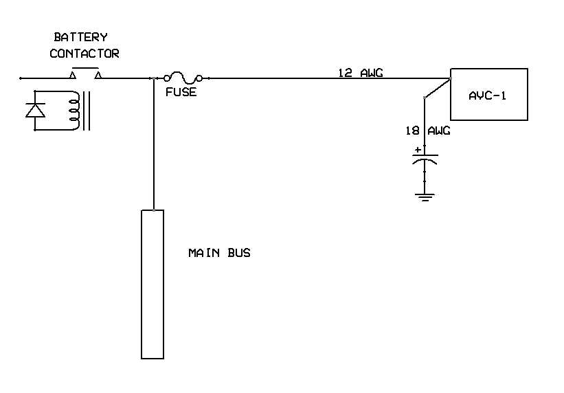
| Quote: | I put those fuses in based on the recommended design available from B&C for the AVC-1 voltage regulator. They are slow-blow fuses with steep curves for inrush and thermal overloads. I prefer not to have these in the system, but now need to decide if I should seek feedback from B&C on their design? I attached the AVC-1 wiring diagram from B&C for your review.
|
The electrical system needs to be protected from a shorted alternator "B" lead.
That fuse should be located at the battery contactor end of the B lead.
| Quote: | Yes you are correct about the B lead. I have a 20A rated permanent magnet AC generator. Not a real "alternator" with greater ratings. It connects directly into the VR unlike the example in Z101B. How should I take care of this scenario? Â
|
Consider what will happen if the battery contactor fails open shortly after takeoff.
You will not know it because everything on the main bus keeps working, powered by the alternator.
The engine keeps running off from the battery until the battery goes dead. Then it quits, but you won't know why.
To prevent that scenario, connect the secondary fuel pump and secondary ignition to the main power bus.
| Quote: | Thank you! What a great catch. I follow your logic and intend on connecting the Secondaries to the main bus.  Curious if you recommend mounting the contactor with the cap down as suggested by White-Rodgers Contactors?
|
Consider using Bob's Z-101
http://www.aeroelectric.com/PPS/Adobe_Architecture_Pdfs/Z101B.pdf
Notice that in Z-101B, neither the main power bus nor the battery bus are protected by a fuse.
| Quote: | The question I have that arises is if the fusible links in the circuit are any different than providing a slow-blow fuse?Â
The fuses are very specific to this design with the AVC-1 VR. The MIDI fuse curves and information are attached. I would greatly appreciate any more feedback you may have after review.
|
 Â
The engine bus in Z-101B has two power sources: the battery and the alternator.
| Quote: | I am trying to work through your suggestion to use Z01B as a design basis for the Batt and Batt/Alt sources for the main bus. The way my circuit works is it has two sources I think. To confirm: My diagram shows 1st the master turns on the battery contactor and brings in the battery to the main bus, then the Batt/Alt switch point brings in the alternator field so to speak and then two sources are on the main bus. I probably just need to look a little harder so bare with me. Thanks!
|
It probably doesn't matter, but the part numbers for the fuel-level-sender resistors indicate 475ohms, not 470.
| Quote: | You're correct I bought 475ohms and need to see if I can source the 470ohm resistors. I wish I could just apply a correction factor for the input...
|
If you use a terminal strip, do not depend on the screw to make the electrical connection.
Put the 2 or 3 wires into one ring terminal and solder or crimp. Then put the ring terminal under the screw.
A loose screw will not affect the connection. Use blue Loctite on screw threads.
| Quote: | Very good advice. I am grateful. Is there a better way to install the resistors?Â
|
Regards
Rick
On Mon, Feb 15, 2021 at 9:31 AM user9253 <fransew(at)gmail.com (fransew(at)gmail.com)> wrote:
| Quote: | --> AeroElectric-List message posted by: "user9253" <fransew(at)gmail.com (fransew(at)gmail.com)>
The symbol for a 1N4005 has a straight line. The symbol on your drawing is for a zener diode.
The 1N4005 diode in series with the low voltage warning light is backwards and will prevent illumination.
What is the purpose of those diodes in series with warning lights?
If those warning lights are LEDs, then they need series resistors unless they are already inside of the warning lights.
Like others have said, get rid of the avionics switch and relay. They serve no useful purpose.
Connect avionics to the main power bus.
Remove that fuse between the battery contactor and the main power bus.
If it blows, everything goes dark. There is a reason that fuse is not on Bob's drawings.
The same applies to the battery bus fuse. Either eliminate it or increase its size to 60 amps.
The electrical system needs to be protected from a shorted alternator "B" lead.
That fuse should be located at the battery contactor end of the B lead.
Consider what will happen if the battery contactor fails open shortly after takeoff.
You will not know it because everything on the main bus keeps working, powered by the alternator.
The engine keeps running off from the battery until the battery goes dead. Then it quits, but you won't know why.
To prevent that scenario, connect the secondary fuel pump and secondary ignition to the main power bus.
Consider using Bob's Z-101
http://www.aeroelectric.com/PPS/Adobe_Architecture_Pdfs/Z101B.pdf
Notice that in Z-101B, neither the main power bus nor the battery bus are protected by a fuse.
The engine bus in Z-101B has two power sources: the battery and the alternator.
It probably doesn't matter, but the part numbers for the fuel-level-sender resistors indicate 475ohms, not 470.
If you use a terminal strip, do not depend on the screw to make the electrical connection.
Put the 2 or 3 wires into one ring terminal and solder or crimp. Then put the ring terminal under the screw.
A loose screw will not affect the connection. Use blue Loctite on screw threads.
--------
Joe Gores
Read this topic online here:
http://forums.matronics.com/viewtopic.php?p=500706#500706
===========
-
Electric-List" rel="noreferrer" target="_blank">http://www.matronics.com/Navigator?AeroElectric-List
===========
FORUMS -
eferrer" target="_blank">http://forums.matronics.com
===========
WIKI -
errer" target="_blank">http://wiki.matronics.com
===========
b Site -
     -Matt Dralle, List Admin.
rel="noreferrer" target="_blank">http://www.matronics.com/contribution
===========
|
| | - The Matronics AeroElectric-List Email Forum - | | | Use the List Feature Navigator to browse the many List utilities available such as the Email Subscriptions page, Archive Search & Download, 7-Day Browse, Chat, FAQ, Photoshare, and much more:
http://www.matronics.com/Navigator?AeroElectric-List |
|
| Description: |
|
Download |
| Filename: |
Littelfuse_MIDI_Datasheet.pdf |
| Filesize: |
535.33 KB |
| Downloaded: |
203 Time(s) |
|
|
| Back to top |
|
|
yellowduckduo(at)gmail.co
Guest
|
| Posted: Mon Feb 15, 2021 12:04 pm Post subject: DC Wiring Diagrams for SPA Panther LS |
|
|
One way of dealing with the EIS resistors is to route the wires through

a small box with the resistors in the box.  That provides strain relief

for the relatively fragile resistors.  Another is to tie the resistors

to a strip of perforated circuit board and enclose it with shrinkwrap or

self fusing tape.


Please just give a reference to a website rather than the large attachments.

Ken
| | - The Matronics AeroElectric-List Email Forum - | | | Use the List Feature Navigator to browse the many List utilities available such as the Email Subscriptions page, Archive Search & Download, 7-Day Browse, Chat, FAQ, Photoshare, and much more:
http://www.matronics.com/Navigator?AeroElectric-List |
|
|
|
| Back to top |
|
|
Ceengland
Joined: 11 Oct 2020
Posts: 378
Location: MS
|
| Posted: Mon Feb 15, 2021 12:34 pm Post subject: DC Wiring Diagrams for SPA Panther LS |
|
|
On Mon, Feb 15, 2021 at 2:13 PM C&K <yellowduckduo(at)gmail.com (yellowduckduo(at)gmail.com)> wrote:
| Quote: | --> AeroElectric-List message posted by: C&K <yellowduckduo(at)gmail.com (yellowduckduo(at)gmail.com)>
One way of dealing with the EIS resistors is to route the wires through
a small box with the resistors in the box. That provides strain relief
for the relatively fragile resistors. Another is to tie the resistors
to a strip of perforated circuit board and enclose it with shrinkwrap or
self fusing tape.
|
With proper strain relief, a slightly higher wattage resistor can be used (for physical robustness) and one lead can be crimped directly in the connector of choice. Other end soldered, or crimped with butt splice to wire. Shrink insulation over  everything.
On detecting alternator power loss: That should be handled with a low voltage monitor/warning system (standalone or within the EFIS/engine monitor). With set point ~1V below alternator output voltage, you'll know if you lose the alternator.
Charlie
Charlie
| | - The Matronics AeroElectric-List Email Forum - | | | Use the List Feature Navigator to browse the many List utilities available such as the Email Subscriptions page, Archive Search & Download, 7-Day Browse, Chat, FAQ, Photoshare, and much more:
http://www.matronics.com/Navigator?AeroElectric-List |
|
_________________
Charlie |
|
| Back to top |
|
|
user9253
Joined: 28 Mar 2008
Posts: 1908
Location: Riley TWP Michigan
|
| Posted: Mon Feb 15, 2021 1:33 pm Post subject: Re: DC Wiring Diagrams for SPA Panther LS |
|
|
No, incandescent lamps do not need series resistors.

You are correct that B&C shows a fuse between the battery contactor and the main power bus.

But thousands of airplanes are flying without that fuse.  Bob N does not recommend it.

Do a good job installing the main power bus feeder to be sure that it will not short out,

especially where it goes through the firewall.  Then that fuse is not needed.

B&C also shows a fuse at the battery contactor end of the regulator "B" lead.  That one IS needed.

On your drawing, there is fuse on the right side of the battery contactor.  Rotate that fuse 90 degrees CCW.

Then interchange the wire going to the regulator with the one going to the main power bus.

See attached picture.

I do not know about the contactor mounting.  Follow the manufacturer's recommendation.

Fusible links are more robust than fuses.  But either will work if installed correctly using the proper size.

Those 5 extra ohms will not make any difference at all in the fuel level display.  Don't worry about it.

12AWG wire going to the capacitor is overkill.  18 AWG wire is easier to work with.

I noticed "OUTPUT AT 12.8V" on your schematic.  The voltage regulator

output should be set at 13.8 minimum.  14.2 is volts better.

The PTT wire going to the mic jack tip is not needed unless you will use a hand held mic that has a PTT switch.
| | - The Matronics AeroElectric-List Email Forum - | | | Use the List Feature Navigator to browse the many List utilities available such as the Email Subscriptions page, Archive Search & Download, 7-Day Browse, Chat, FAQ, Photoshare, and much more:
http://www.matronics.com/Navigator?AeroElectric-List |
|
| Description: |
|
| Filesize: |
13.08 KB |
| Viewed: |
5002 Time(s) |
|
_________________
Joe Gores |
|
| Back to top |
|
|
user9253
Joined: 28 Mar 2008
Posts: 1908
Location: Riley TWP Michigan
|
| Posted: Mon Feb 15, 2021 1:51 pm Post subject: Re: DC Wiring Diagrams for SPA Panther LS |
|
|
On your schematic, put a dot where wires connect to each other.

On page E9, it is very confusing about which wires are connected and which are not.

The tachometer might not be wired right, but it is hard to tell.
| | - The Matronics AeroElectric-List Email Forum - | | | Use the List Feature Navigator to browse the many List utilities available such as the Email Subscriptions page, Archive Search & Download, 7-Day Browse, Chat, FAQ, Photoshare, and much more:
http://www.matronics.com/Navigator?AeroElectric-List |
|
_________________
Joe Gores |
|
| Back to top |
|
|
jsajpf
Joined: 21 Feb 2019
Posts: 8
|
| Posted: Tue Feb 16, 2021 5:34 am Post subject: Re: DC Wiring Diagrams for SPA Panther LS |
|
|
Rick,

Does the aircraft pitch trim system include a manual trim wheel or lever, or is the sole means of pitch trim the electric system?

The electric trim circuit lacks a combination "arm" and "command" input (think of the split trim switch on many GA type certificated aircraft).  Only a "command" input is shown.  I think this single input is common in E/AB airplanes but I personally do not favor it.

I think your relay circuit for pitch trim (rather than direct switching of motor current with a momentary switch) provides a measure of protection against uncommanded or runaway pitch trim, in that an opposite direction command at the switch will change the state of the motor legs, at least stopping further trim movement while the switch is held.

I think a cutout switch to remove power from the motor circuit is advisable, located such that a free hand can get get to it, perhaps while on its way to the manual trim control (mine will be next to the manual trim wheel).  Removal of power from the existing circuit would require the pilot to locate and open the trim circuit breaker while also fighting the trim forces, and countering the uncommanded trim in some way (e.g. restrain the manual trim control or holding opposite direction trim command with the switch).

Does the trim servo connect to the trim system in a way that allows the servo input to be manually overriden; meaning a slip feature that would allow holding the manual trim input against servo motion?  Perhaps the servo itself has this feature?

These system safety measures may all be unnecessary on the class of airplane you're building.  I advise you to consider what sort of trim induced control forces you might expect at the speeds and configuration combinations of the airplane, and then look to see how quickly the electric system might get you into trouble; rate of trim, range of trim, etc.  The airplane I will build is noted for trim sensitivity at cruise speeds so I'll have at least two trim speeds (slow for flaps up, faster for flaps down).  There are systems that allow continuously variable speeds as well, typically based on airspeed.

I've seen some all-electric trim systems incorporate a direction reversal switch that would allow a measure of control redundancy should a single direction fail.

Well done on the wiring diagrams!

John
| | - The Matronics AeroElectric-List Email Forum - | | | Use the List Feature Navigator to browse the many List utilities available such as the Email Subscriptions page, Archive Search & Download, 7-Day Browse, Chat, FAQ, Photoshare, and much more:
http://www.matronics.com/Navigator?AeroElectric-List |
|
|
|
| Back to top |
|
|
|
|
You cannot post new topics in this forum
You cannot reply to topics in this forum
You cannot edit your posts in this forum
You cannot delete your posts in this forum
You cannot vote in polls in this forum
You cannot attach files in this forum
You can download files in this forum
|
Powered by phpBB © 2001, 2005 phpBB Group
|

