 |
Matronics Email Lists
Web Forum Interface to the Matronics Email Lists
|
| View previous topic :: View next topic |
| Author |
Message |
David Lamphere
Joined: 20 Oct 2019
Posts: 19
Location: Culpeper, Virginia
|
 Posted: Wed Jan 13, 2021 8:11 am Post subject: Alternator bench test Posted: Wed Jan 13, 2021 8:11 am Post subject: Alternator bench test |
 |
|
Twice I have sent a PlanePower (internal volt regulator) back to Hartzell as it is not charging.

Both times they have told me it checks out OK on the bench.


I have checked wiring 3 times without finding a culprit. The last thing I did before sending it to them was set it up on the bench. It did not work (would not charge). Let me describe what I set up - perhaps I am missing something. I tried to make the setup as simple as possible.
| | - The Matronics AeroElectric-List Email Forum - | | | Use the List Feature Navigator to browse the many List utilities available such as the Email Subscriptions page, Archive Search & Download, 7-Day Browse, Chat, FAQ, Photoshare, and much more:
http://www.matronics.com/Navigator?AeroElectric-List |
|
| Description: |
|

Download |
| Filename: |
scan20210113.pdf |
| Filesize: |
100.49 KB |
| Downloaded: |
205 Time(s) |
|
|
| Back to top |
|
 |
edwclg
Joined: 30 Dec 2007
Posts: 18
|
| Posted: Wed Jan 13, 2021 9:07 am Post subject: Alternator bench test |
|
|
I recently had a problem and replaced the internal VR and in doing so
did not tighten the B lead to alt enough.
No Charge. Tightened and now works perfectly. May have been the
original problem as field cb never tripped.
Ed
On Wed, Jan 13, 2021 at 11:20 AM David and Elaine Lamphere
<dalamphere(at)comcast.net> wrote:
| Quote: |
Twice I have sent a PlanePower (internal volt regulator) back to Hartzell as it is not charging.
Both times they have told me it checks out OK on the bench.
I have checked wiring 3 times without finding a culprit. The last thing I did before sending it to them was set it up on the bench. It did not work (would not charge). Let me describe what I set up - perhaps I am missing something. I tried to make the setup as simple as possible.
|
| | - The Matronics AeroElectric-List Email Forum - | | | Use the List Feature Navigator to browse the many List utilities available such as the Email Subscriptions page, Archive Search & Download, 7-Day Browse, Chat, FAQ, Photoshare, and much more:
http://www.matronics.com/Navigator?AeroElectric-List |
|
|
|
| Back to top |
|
|
David Lamphere
Joined: 20 Oct 2019
Posts: 19
Location: Culpeper, Virginia
|
| Posted: Wed Jan 13, 2021 9:47 am Post subject: Alternator bench test |
|
|
Thatâs interesting - what would be your opinion of my cruse bench setup?
Would it work?
On Jan 13, 2021, at 12:03 PM, edward Clegg <edwclg(at)gmail.com> wrote:
I recently had a problem and replaced the internal VR and in doing so
did not tighten the B lead to alt enough.
No Charge. Tightened and now works perfectly. May have been the
original problem as field cb never tripped.
Ed
On Wed, Jan 13, 2021 at 11:20 AM David and Elaine Lamphere
<dalamphere(at)comcast.net> wrote:
| Quote: |
Twice I have sent a PlanePower (internal volt regulator) back to Hartzell as it is not charging.
Both times they have told me it checks out OK on the bench.
I have checked wiring 3 times without finding a culprit. The last thing I did before sending it to them was set it up on the bench. It did not work (would not charge). Let me describe what I set up - perhaps I am missing something. I tried to make the setup as simple as possible.
|
| | - The Matronics AeroElectric-List Email Forum - | | | Use the List Feature Navigator to browse the many List utilities available such as the Email Subscriptions page, Archive Search & Download, 7-Day Browse, Chat, FAQ, Photoshare, and much more:
http://www.matronics.com/Navigator?AeroElectric-List |
|
|
|
| Back to top |
|
|
user9253
Joined: 28 Mar 2008
Posts: 1908
Location: Riley TWP Michigan
|
| Posted: Wed Jan 13, 2021 10:24 am Post subject: Re: Alternator bench test |
|
|
Have you measured the field current? If so, what is it?
| | - The Matronics AeroElectric-List Email Forum - | | | Use the List Feature Navigator to browse the many List utilities available such as the Email Subscriptions page, Archive Search & Download, 7-Day Browse, Chat, FAQ, Photoshare, and much more:
http://www.matronics.com/Navigator?AeroElectric-List |
|
_________________
Joe Gores |
|
| Back to top |
|
|
jluckey(at)pacbell.net
Guest
|
| Posted: Wed Jan 13, 2021 10:52 am Post subject: Alternator bench test |
|
|
David,
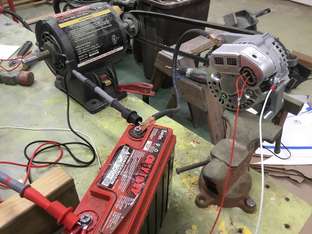
During Covid hibernation I had some time to bench-test a couple of alternators and I found that some were sensitive to low RPM. In other words, some alternators need to spin pretty fast to work properly.
I used a test fixture (picture attached) and used a 3/4 horsepower motor from my shop sander to drive it. That motor spins at 3450 RPM and I had a pulley configuration of about 1.2:1. So I'm guestimating that the alternator was turning somewhere around 2800 RPM.
Some alternator/regulator combinations that I tested would not self-start at that low RPM. If I momentarily jumped the field, it would generate electricity and regulate normally. When I changed the pulley arrangement to get higher alternator RPM, it would self-start.
Some regulators have a self-starting feature where they won't turn-on until they reach some minimum RPM. It is designed to keep power off the field when the engine is not turning. I have no idea about how the Plane Power devices are supposed to work. (I was testing automotive alternators & regulators)
What I learned:
1. Some alternator/regulator combinations won't work properly until they hit some minimum RPM
2. Manually jumping the field to get it started can be valuable 'cuz it showed the regulator could regulate (was not DOA)
However, Jumping the field may be more challenging on an internal regulator unit???
My test fixture is UGLY. But it worked well and was fast & cheap to build. The 3/4 HP motor mounts to the right on the 2 studs that are sticking up. I would have preferred to use a more powerful motor, at least 1 HP, but none was available, so I went with what I had. The motor would bog-down with about 25 Amps of load on the alternator.
-Jeff
On Wednesday, January 13, 2021, 09:56:20 AM PST, David and Elaine Lamphere <dalamphere(at)comcast.net> wrote:
--> AeroElectric-List message posted by: David and Elaine Lamphere <dalamphere(at)comcast.net (dalamphere(at)comcast.net)>
Thatâs interesting - what would be your opinion of my cruse bench setup?
Would it work?
On Jan 13, 2021, at 12:03 PM, edward Clegg <edwclg(at)gmail.com (edwclg(at)gmail.com)> wrote:
--> AeroElectric-List message posted by: edward Clegg <edwclg(at)gmail.com (edwclg(at)gmail.com)>
I recently had a problem and replaced the internal VR and in doing so
did not tighten the B lead to alt enough.
No Charge. Tightened and now works perfectly. May have been the
original problem as field cb never tripped.
Ed
On Wed, Jan 13, 2021 at 11:20 AM David and Elaine Lamphere
<dalamphere(at)comcast.net (dalamphere(at)comcast.net)> wrote:
| Quote: | Twice I have sent a PlanePower (internal volt regulator) back to Hartzell as it is not charging.
|
| Quote: | Both times they have told me it checks out OK on the bench.
|
| Quote: | I have checked wiring 3 times without finding a culprit. The last thing I did before sending it to them was set it up on the bench. It did not work (would not charge). Let me describe what I set up - perhaps I am missing something. I tried to make the setup as simple as possible.
|
<================
AeroElectric-List" target="_blank">http://www.matronics.com/Navigator?Aer - MATRONICS WEB FORUMS -
http://wiki.matronics.com[/url]
http://www.matronics.c=
| | - The Matronics AeroElectric-List Email Forum - | | | Use the List Feature Navigator to browse the many List utilities available such as the Email Subscriptions page, Archive Search & Download, 7-Day Browse, Chat, FAQ, Photoshare, and much more:
http://www.matronics.com/Navigator?AeroElectric-List |
|
| Description: |
|
| Filesize: |
1.55 MB |
| Viewed: |
3577 Time(s) |
|
|
|
| Back to top |
|
|
David Lamphere
Joined: 20 Oct 2019
Posts: 19
Location: Culpeper, Virginia
|
| Posted: Wed Jan 13, 2021 11:02 am Post subject: Alternator bench test |
|
|
Joe,
I verified that there is a slight magnetic field generated.
when I get the unit back from Hartzell, Iâll see about measuring that.
They claim it passes production functional test. Very frustrating.
4 connectons plus chassis ground - and one connection is just for a warning light.
Hard hard can it be? (famous last words)
Thanks,
Dave
On Jan 13, 2021, at 1:24 PM, user9253 <fransew(at)gmail.com> wrote:
Have you measured the field current? If so, what is it?
--------
Joe Gores
Read this topic online here:
http://forums.matronics.com/viewtopic.php?p=500199#500199
| | - The Matronics AeroElectric-List Email Forum - | | | Use the List Feature Navigator to browse the many List utilities available such as the Email Subscriptions page, Archive Search & Download, 7-Day Browse, Chat, FAQ, Photoshare, and much more:
http://www.matronics.com/Navigator?AeroElectric-List |
|
|
|
| Back to top |
|
|
David Lamphere
Joined: 20 Oct 2019
Posts: 19
Location: Culpeper, Virginia
|
| Posted: Wed Jan 13, 2021 12:00 pm Post subject: Alternator bench test |
|
|
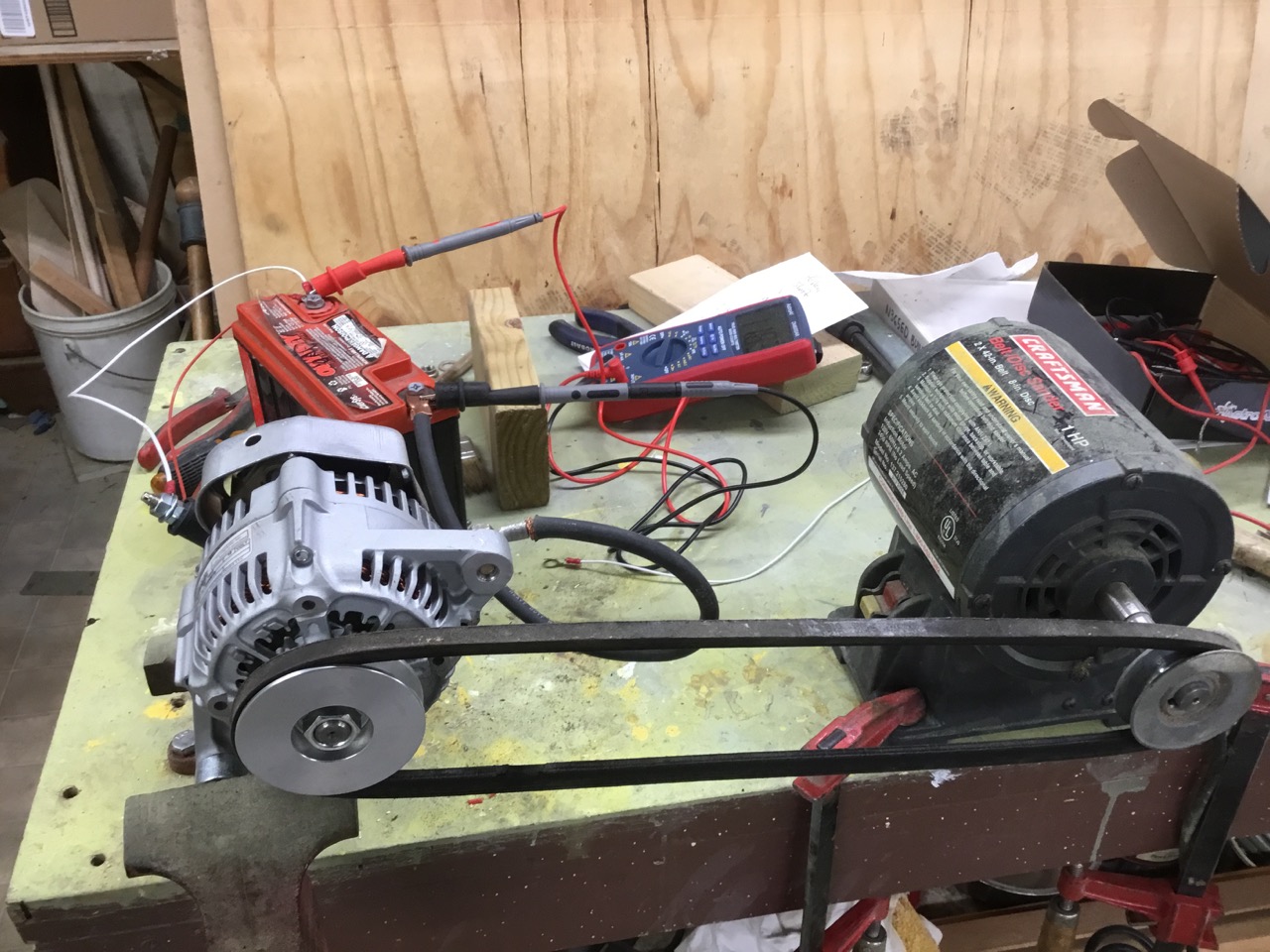
Sounds familiar - I used a belt sander motor alsoâ¦The question posed is schematically should it work?
Hereâs what I had:
On Jan [img]cid:3FA59B26-14C7-4FF1-838E-3835219EB84E(at)hsd1.va.comcast.net.[/img]
[img]cid:351DDFDD-EB89-44D5-B8D2-A225D115818E(at)hsd1.va.comcast.net.[/img]
13, 2021, at 1:47 PM, Jeff Luckey <jluckey(at)pacbell.net (jluckey(at)pacbell.net)> wrote:
David,
During Covid hibernation I had some time to bench-test a couple of alternators and I found that some were sensitive to low RPM. In other words, some alternators need to spin pretty fast to work properly.
I used a test fixture (picture attached) and used a 3/4 horsepower motor from my shop sander to drive it. That motor spins at 3450 RPM and I had a pulley configuration of about 1.2:1. So I'm guestimating that the alternator was turning somewhere around 2800 RPM.
Some alternator/regulator combinations that I tested would not self-start at that low RPM. If I momentarily jumped the field, it would generate electricity and regulate normally. When I changed the pulley arrangement to get higher alternator RPM, it would self-start.
Some regulators have a self-starting feature where they won't turn-on until they reach some minimum RPM. It is designed to keep power off the field when the engine is not turning. I have no idea about how the Plane Power devices are supposed to work. (I was testing automotive alternators & regulators)
What I learned:
1. Some alternator/regulator combinations won't work properly until they hit some minimum RPM
2. Manually jumping the field to get it started can be valuable 'cuz it showed the regulator could regulate (was not DOA)
However, Jumping the field may be more challenging on an internal regulator unit???
My test fixture is UGLY. But it worked well and was fast & cheap to build. The 3/4 HP motor mounts to the right on the 2 studs that are sticking up. I would have preferred to use a more powerful motor, at least 1 HP, but none was available, so I went with what I had. The motor would bog-down with about 25 Amps of load on the alternator.
-Jeff
| | - The Matronics AeroElectric-List Email Forum - | | | Use the List Feature Navigator to browse the many List utilities available such as the Email Subscriptions page, Archive Search & Download, 7-Day Browse, Chat, FAQ, Photoshare, and much more:
http://www.matronics.com/Navigator?AeroElectric-List |
|
| Description: |
|
| Filesize: |
296.99 KB |
| Viewed: |
3562 Time(s) |

|
| Description: |
|
| Filesize: |
333.33 KB |
| Viewed: |
3562 Time(s) |
|
|
|
| Back to top |
|
|
jluckey(at)pacbell.net
Guest
|
| Posted: Wed Jan 13, 2021 12:42 pm Post subject: Alternator bench test |
|
|
David,
I don't know the Plane Power device, so I can't determine if it is wired correctly.
But, based on your pulley configuration, the alternator is turning slower than the motor. So if the Plane Power setup has a minimum RPM, it is very likely turning too slowly in your test fixture.
Wish I could be or more help. There are lots of Listers who know more about the Plane Power equipment.
-Jeff
On Wednesday, January 13, 2021, 12:15:47 PM PST, David and Elaine Lamphere <dalamphere(at)comcast.net> wrote:
Sounds familiar - I used a belt sander motor alsoâ¦The question posed is schematically should it work?
Hereâs what I had:
On Jan [img]cid:BiXRcr3wXfVtw1mEZ5Ht[/img]
[img]cid:ihixkEZvwZ3c5hL9z9lr[/img]
13, 2021, at 1:47 PM, Jeff Luckey <jluckey(at)pacbell.net (jluckey(at)pacbell.net)> wrote:
David,
During Covid hibernation I had some time to bench-test a couple of alternators and I found that some were sensitive to low RPM. In other words, some alternators need to spin pretty fast to work properly.
I used a test fixture (picture attached) and used a 3/4 horsepower motor from my shop sander to drive it. That motor spins at 3450 RPM and I had a pulley configuration of about 1.2:1. So I'm guestimating that the alternator was turning somewhere around 2800 RPM.
Some alternator/regulator combinations that I tested would not self-start at that low RPM. If I momentarily jumped the field, it would generate electricity and regulate normally. When I changed the pulley arrangement to get higher alternator RPM, it would self-start.
Some regulators have a self-starting feature where they won't turn-on until they reach some minimum RPM. It is designed to keep power off the field when the engine is not turning. I have no idea about how the Plane Power devices are supposed to work. (I was testing automotive alternators & regulators)
What I learned:
1. Some alternator/regulator combinations won't work properly until they hit some minimum RPM
2. Manually jumping the field to get it started can be valuable 'cuz it showed the regulator could regulate (was not DOA)
However, Jumping the field may be more challenging on an internal regulator unit???
My test fixture is UGLY. But it worked well and was fast & cheap to build. The 3/4 HP motor mounts to the right on the 2 studs that are sticking up. I would have preferred to use a more powerful motor, at least 1 HP, but none was available, so I went with what I had. The motor would bog-down with about 25 Amps of load on the alternator.
-Jeff
| | - The Matronics AeroElectric-List Email Forum - | | | Use the List Feature Navigator to browse the many List utilities available such as the Email Subscriptions page, Archive Search & Download, 7-Day Browse, Chat, FAQ, Photoshare, and much more:
http://www.matronics.com/Navigator?AeroElectric-List |
|
| Description: |
|
| Filesize: |
333.33 KB |
| Viewed: |
3562 Time(s) |

|
| Description: |
|
| Filesize: |
296.99 KB |
| Viewed: |
3562 Time(s) |

|
|
|
| Back to top |
|
|
Ceengland
Joined: 11 Oct 2020
Posts: 379
Location: MS
|
| Posted: Wed Jan 13, 2021 1:03 pm Post subject: Alternator bench test |
|
|
David,
What do the PP instructions for that particular alt look like?
At least one PP doc says that one of the F terminals should be grounded, unless there's a particular type of regulator in use.
Part No. 10-1001
Installation Instructions
1. Disconnect aircraft battery,
2. tnstall alternator per included drawing.
3. Refer to appropriate engine and airframe service manuals for belt tension and bolt
torques.
4. Install battery wire with MS2517l-2S terminal nipple on 6mm output terminal
and torque to 50 in. lb.
5. lnstall ground wire to any of the three 5mm studs on rear of alternator and torque
to 35 in. lb.
6. Install field wire with MS2517l-1S terminal nipple to Fl terminal on rear of
alternator and torque to 20 in. lb.
7. NOTE: F2 terminal to remain grounded with ground strap UNLESS aircraft
voltage regulator is a t1pe "A" regulator using a2-wire field circuit, in this case
rezulator to Fl and F2 terminals. torque to 20 in. lb.
8. If aircraft is equipped with an "alternator out light" circuit, connect that wire to
the AUX terminal and torque to 20 in. lbs. Other wise leave AUX terminal open.
9. Reconnect aircraft battery.
10. Start aircraft and check alternator output for proper operation.
Charlie
On Wed, Jan 13, 2021 at 2:09 PM David and Elaine Lamphere <dalamphere(at)comcast.net (dalamphere(at)comcast.net)> wrote:
| Quote: | Sounds familiar - I used a belt sander motor alsoâ¦The question posed is schematically should it work?
Hereâs what I had:
On Jan [img]cid:176fd82fab62b008e9e1[/img]Â
[img]cid:176fd82fab62cb5673d2[/img]
13, 2021, at 1:47 PM, Jeff Luckey <jluckey(at)pacbell.net (jluckey(at)pacbell.net)> wrote:
David,
During Covid hibernation I had some time to bench-test a couple of alternators and I found that some were sensitive to low RPM. In other words, some alternators need to spin pretty fast to work properly.
I used a test fixture (picture attached) and used a 3/4 horsepower motor from my shop sander to drive it. That motor spins at 3450 RPM and I had a pulley configuration of about 1.2:1. So I'm guestimating that the alternator was turning somewhere around 2800 RPM.
Some alternator/regulator combinations that I tested would not self-start at that low RPM. If I momentarily jumped the field, it would generate electricity and regulate normally. When I changed the pulley arrangement to get higher alternator RPM, it would self-start.
Some regulators have a self-starting feature where they won't turn-on until they reach some minimum RPM. It is designed to keep power off the field when the engine is not turning. I have no idea about how the Plane Power devices are supposed to work. (I was testing automotive alternators & regulators)
What I learned:
1. Some alternator/regulator combinations won't work properly until they hit some minimum RPM
2. Manually jumping the field to get it started can be valuable 'cuz it showed the regulator could regulate (was not DOA)
However, Jumping the field may be more challenging on an internal regulator unit???
My test fixture is UGLY. But it worked well and was fast & cheap to build. The 3/4 HP motor mounts to the right on the 2 studs that are sticking up. I would have preferred to use a more powerful motor, at least 1 HP, but none was available, so I went with what I had. The motor would bog-down with about 25 Amps of load on the alternator.
-Jeff
|
| | - The Matronics AeroElectric-List Email Forum - | | | Use the List Feature Navigator to browse the many List utilities available such as the Email Subscriptions page, Archive Search & Download, 7-Day Browse, Chat, FAQ, Photoshare, and much more:
http://www.matronics.com/Navigator?AeroElectric-List |
|
| Description: |
|
| Filesize: |
296.99 KB |
| Viewed: |
3562 Time(s) |
|
| Description: |
|
| Filesize: |
333.33 KB |
| Viewed: |
3562 Time(s) |

|
_________________
Charlie |
|
| Back to top |
|
|
nuckolls.bob(at)aeroelect
Guest
|
| Posted: Wed Jan 13, 2021 1:53 pm Post subject: Alternator bench test |
|
|
At 10:05 AM 1/13/2021, you wrote:
| Quote: | Twice I have sent a PlanePower (internal volt regulator) back to Hartzell as it is not charging.
Both times they have told me it checks out OK on the bench.
I have checked wiring 3 times without finding a culprit. The last thing I did before sending it to them was set it up on the bench. It did not work (would not charge). Let me describe what I set up - perhaps I am missing something. I tried to make the setup as simple as possible. |
What is the rpm of your driving motor. What are your
pulley diameters. There are two, critical rpm numbers
for an alternator:
(1) minimum speed for full ouput
(2) minimum speed for regulation.
An alternator will deliver no energy to your
battery until it's driven at minimum speed
for regulation.
Bob . . .
Un impeachable logic: George Carlin asked, "If black boxes
survive crashes, why don't they make the whole airplane
out of that stuff?"
| | - The Matronics AeroElectric-List Email Forum - | | | Use the List Feature Navigator to browse the many List utilities available such as the Email Subscriptions page, Archive Search & Download, 7-Day Browse, Chat, FAQ, Photoshare, and much more:
http://www.matronics.com/Navigator?AeroElectric-List |
|
|
|
| Back to top |
|
|
David Lamphere
Joined: 20 Oct 2019
Posts: 19
Location: Culpeper, Virginia
|
| Posted: Wed Jan 13, 2021 1:59 pm Post subject: Alternator bench test |
|
|
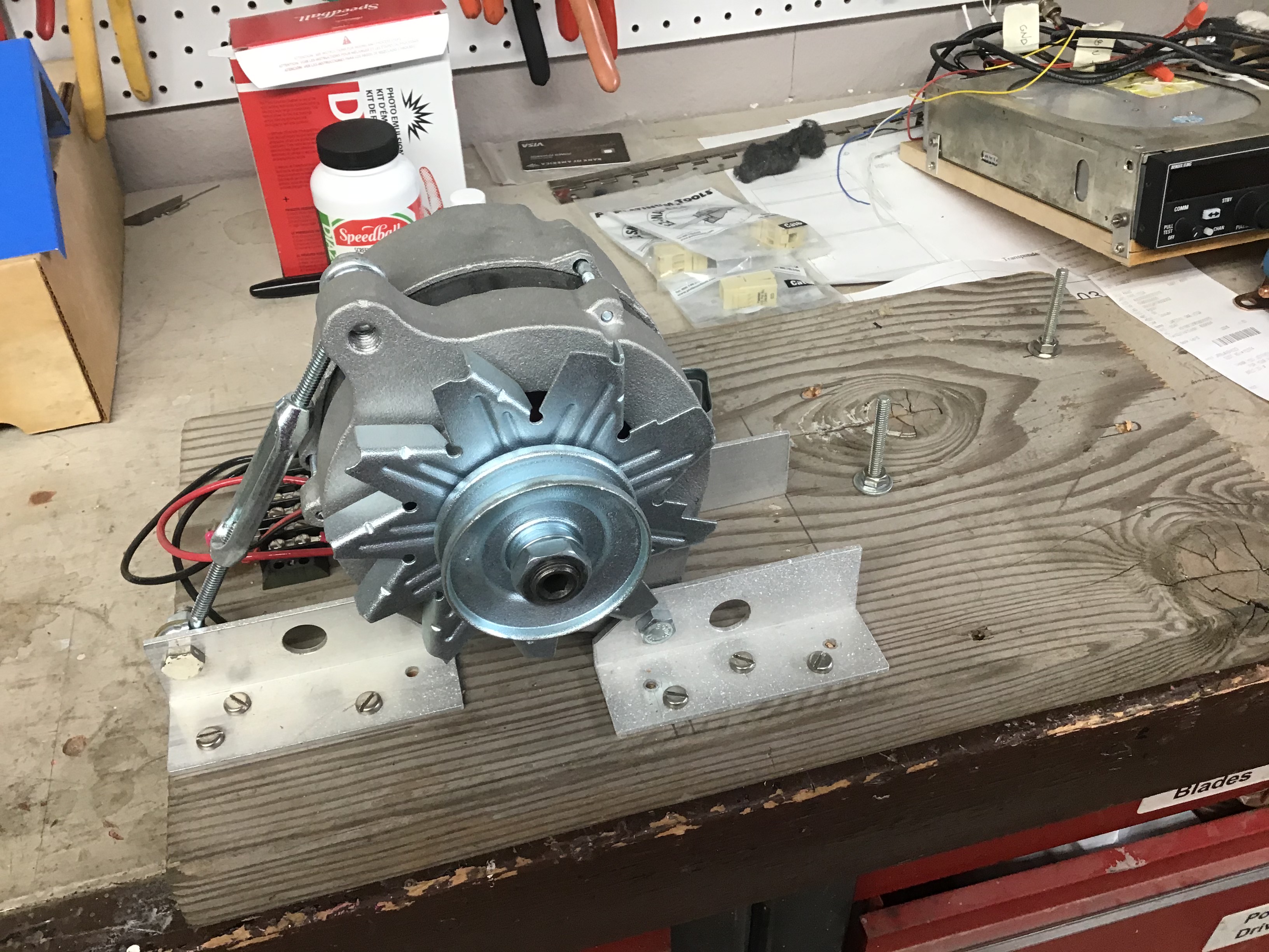
This is an AL12-E160-B (PP 99-9900) - internal regulator alternatorInstructions:
[img]cid:213C0463-94F3-4AA4-B9E7-232002823D35(at)hsd1.va.comcast.net.[/img]
field cable wired correctly pins 3 + 2 jumped, red wire (top or most left is #3 view from rear)
pin 1 white wire for alternator out lamp
So what else do I need?
David
On Jan 13, 2021, at 3:52 PM, Charlie England <ceengland7(at)gmail.com (ceengland7(at)gmail.com)> wrote:David,
What do the PP instructions for that particular alt look like?
At least one PP doc says that one of the F terminals should be grounded, unless there's a particular type of regulator in use.
Part No. 10-1001Installation Instructions1. Disconnect aircraft battery,2. tnstall alternator per included drawing.3. Refer to appropriate engine and airframe service manuals for belt tension and bolttorques.4. Install battery wire with MS2517l-2S terminal nipple on 6mm output terminaland torque to 50 in. lb.5. lnstall ground wire to any of the three 5mm studs on rear of alternator and torqueto 35 in. lb.6. Install field wire with MS2517l-1S terminal nipple to Fl terminal on rear ofalternator and torque to 20 in. lb.7. NOTE: F2 terminal to remain grounded with ground strap UNLESS aircraftvoltage regulator is a t1pe "A" regulator using a2-wire field circuit, in this caserezulator to Fl and F2 terminals. torque to 20 in. lb.8. If aircraft is equipped with an "alternator out light" circuit, connect that wire tothe AUX terminal and torque to 20 in. lbs. Other wise leave AUX terminal open.9. Reconnect aircraft battery.10. Start aircraft and check alternator output for proper operation.
Charlie
On Wed, Jan 13, 2021 at 2:09 PM David and Elaine Lamphere <dalamphere(at)comcast.net (dalamphere(at)comcast.net)> wrote:
| Quote: | Sounds familiar - I used a belt sander motor alsoâ¦The question posed is schematically should it work?
Hereâs what I had:
On Jan <alt-setup1.jpeg>
<alt-setup2.jpeg>
13, 2021, at 1:47 PM, Jeff Luckey <jluckey(at)pacbell.net (jluckey(at)pacbell.net)> wrote:
David,
During Covid hibernation I had some time to bench-test a couple of alternators and I found that some were sensitive to low RPM. In other words, some alternators need to spin pretty fast to work properly.
I used a test fixture (picture attached) and used a 3/4 horsepower motor from my shop sander to drive it. That motor spins at 3450 RPM and I had a pulley configuration of about 1.2:1. So I'm guestimating that the alternator was turning somewhere around 2800 RPM.
Some alternator/regulator combinations that I tested would not self-start at that low RPM. If I momentarily jumped the field, it would generate electricity and regulate normally. When I changed the pulley arrangement to get higher alternator RPM, it would self-start.
Some regulators have a self-starting feature where they won't turn-on until they reach some minimum RPM. It is designed to keep power off the field when the engine is not turning. I have no idea about how the Plane Power devices are supposed to work. (I was testing automotive alternators & regulators)
What I learned:
1. Some alternator/regulator combinations won't work properly until they hit some minimum RPM
2. Manually jumping the field to get it started can be valuable 'cuz it showed the regulator could regulate (was not DOA)
However, Jumping the field may be more challenging on an internal regulator unit???
My test fixture is UGLY. But it worked well and was fast & cheap to build. The 3/4 HP motor mounts to the right on the 2 studs that are sticking up. I would have preferred to use a more powerful motor, at least 1 HP, but none was available, so I went with what I had. The motor would bog-down with about 25 Amps of load on the alternator.
-Jeff
|
| | - The Matronics AeroElectric-List Email Forum - | | | Use the List Feature Navigator to browse the many List utilities available such as the Email Subscriptions page, Archive Search & Download, 7-Day Browse, Chat, FAQ, Photoshare, and much more:
http://www.matronics.com/Navigator?AeroElectric-List |
|
| Description: |
|
| Filesize: |
70.21 KB |
| Viewed: |
3561 Time(s) |

|
|
|
| Back to top |
|
|
Ceengland
Joined: 11 Oct 2020
Posts: 379
Location: MS
|
| Posted: Wed Jan 13, 2021 2:34 pm Post subject: Alternator bench test |
|
|
Then your setup looks electrically correct, but as Bob N and others have pointed out, you must turn the alt fast enough to actually generate anything. Suggest asking PP about minimum RPM.
You do need to be sure that the battery is near fully charged for a test like this; you need enough energy to power the field coil in the alternator. You also need it charged because a 70A alternator needs close to 2 HP driving it (and spinning it fast enough) to make full output. If the battery is near full charge when you start the test, it will load the alternator less, increasing the chance that the alternator can supply output.
When you spin up your test rig, have you measured voltage at both the F terminals, and at the B lead terminal, referenced to the battery negative? You should see at least battery voltage at the B terminal, and, until the alternator comes online, battery voltage at the F terminals. The F terminal voltage will vary to maintain the B terminal voltage at set point (should be at least ~14V at B terminal). The initial two measurements will tell you whether your test rig is wired correctly.
Charlie
On Wed, Jan 13, 2021 at 4:06 PM David and Elaine Lamphere <dalamphere(at)comcast.net (dalamphere(at)comcast.net)> wrote:
| Quote: | This is an AL12-E160-B Â (PP 99-9900) - internal regulator alternatorInstructions:
[img]cid:176fdd03cc81fc11f51[/img]
field cable wired correctly pins 3 + 2 jumped, red wire (top or most left is #3 view from rear)
pin 1 white wire for alternator out lamp
So what else do I need?
David
Â
On Jan 13, 2021, at 3:52 PM, Charlie England <ceengland7(at)gmail.com (ceengland7(at)gmail.com)> wrote:
David,
What do the PP instructions for that particular alt look like?
At least one PP doc says that one of the F terminals should be grounded, unless there's a particular type of regulator in use.
Part No. 10-1001
Installation Instructions
1. Disconnect aircraft battery,
2. tnstall alternator per included drawing.
3. Refer to appropriate engine and airframe service manuals for belt tension and bolt
torques.
4. Install battery wire with MS2517l-2S terminal nipple on 6mm output terminal
and torque to 50 in. lb.
5. lnstall ground wire to any of the three 5mm studs on rear of alternator and torque
to 35 in. lb.
6. Install field wire with MS2517l-1S terminal nipple to Fl terminal on rear of
alternator and torque to 20 in. lb.
7. NOTE: F2 terminal to remain grounded with ground strap UNLESS aircraft
voltage regulator is a t1pe "A" regulator using a2-wire field circuit, in this case
rezulator to Fl and F2 terminals. torque to 20 in. lb.
8. If aircraft is equipped with an "alternator out light" circuit, connect that wire to
the AUX terminal and torque to 20 in. lbs. Other wise leave AUX terminal open.
9. Reconnect aircraft battery.
10. Start aircraft and check alternator output for proper operation.
Charlie
On Wed, Jan 13, 2021 at 2:09 PM David and Elaine Lamphere <dalamphere(at)comcast.net (dalamphere(at)comcast.net)> wrote:
| Quote: | Sounds familiar - I used a belt sander motor alsoâ¦The question posed is schematically should it work?
Hereâs what I had:
On Jan <alt-setup1.jpeg>Â
<alt-setup2.jpeg>
13, 2021, at 1:47 PM, Jeff Luckey <jluckey(at)pacbell.net (jluckey(at)pacbell.net)> wrote:
David,
During Covid hibernation I had some time to bench-test a couple of alternators and I found that some were sensitive to low RPM. In other words, some alternators need to spin pretty fast to work properly.
I used a test fixture (picture attached) and used a 3/4 horsepower motor from my shop sander to drive it. That motor spins at 3450 RPM and I had a pulley configuration of about 1.2:1. So I'm guestimating that the alternator was turning somewhere around 2800 RPM.
Some alternator/regulator combinations that I tested would not self-start at that low RPM. If I momentarily jumped the field, it would generate electricity and regulate normally. When I changed the pulley arrangement to get higher alternator RPM, it would self-start.
Some regulators have a self-starting feature where they won't turn-on until they reach some minimum RPM. It is designed to keep power off the field when the engine is not turning. I have no idea about how the Plane Power devices are supposed to work. (I was testing automotive alternators & regulators)
What I learned:
1. Some alternator/regulator combinations won't work properly until they hit some minimum RPM
2. Manually jumping the field to get it started can be valuable 'cuz it showed the regulator could regulate (was not DOA)
However, Jumping the field may be more challenging on an internal regulator unit???
My test fixture is UGLY. But it worked well and was fast & cheap to build. The 3/4 HP motor mounts to the right on the 2 studs that are sticking up. I would have preferred to use a more powerful motor, at least 1 HP, but none was available, so I went with what I had. The motor would bog-down with about 25 Amps of load on the alternator.
-Jeff
|
|
| | - The Matronics AeroElectric-List Email Forum - | | | Use the List Feature Navigator to browse the many List utilities available such as the Email Subscriptions page, Archive Search & Download, 7-Day Browse, Chat, FAQ, Photoshare, and much more:
http://www.matronics.com/Navigator?AeroElectric-List |
|
| Description: |
|
| Filesize: |
70.21 KB |
| Viewed: |
3561 Time(s) |
|
_________________
Charlie |
|
| Back to top |
|
|
David Lamphere
Joined: 20 Oct 2019
Posts: 19
Location: Culpeper, Virginia
|
| Posted: Wed Jan 13, 2021 4:01 pm Post subject: Alternator bench test |
|
|
Thank you for your input. I agree with what you say.
The main reason for trying the bench setup was to eliminate airplane installation variables - it was not charging installed in the plane.
The 2-1/2â pulley on the electric motor turns 3450 rpm
The alternator pulley (looking at the picture - havenât got it back yet) is approximately 3â
perhaps someone has a similar unit and can correct me.
This would amount to the alternator turning 2874 rpm
Mathematically if the engineâs drive pulley is 9â diameter then the engine would be turning 958 rpm when the alternator was turning 2874 rpm - I would expect SOME charging would be going on. I do have a larger diameter pulley in my scrap bin and can rerun the experiment is necessary (when the alternator gets back here). I would guess a 4-1/2 to 5â pulley would work if you wanted to simulate the engine running at 1800 rpm. According to the test graph they supplied (I have attached that to the end of this email) at 2874 rpm it should be outputting > 40 a.
The main reason for the crude setup was to see if it would charge at all, what Voltage would be present when it ran (thinking the regulator might not be working). During the trial run, all I saw was the battery voltage slowly decreasing.
Which brings me to the reason for posting the question - was what I had set up electrically correct? or is there some other load required? Just trying to understand why their bench testing passes and mine doesnât.
I asked Hartzell/PlanePower to advise on what I would need to setup a basic bench test schematic - they declined to offer that info today. They will only help on troubleshooting with it installed in the airplane. I have gone through their troubleshooting procedures and have found nothing so far - ending with flow chart box saying contact technical support.
Thatâs why Iâd like to be sure it is working in the shop before putting it in the plane.
David
On Jan 13, 2021, at 4:48 PM, Robert L. Nuckolls, III <nuckolls.bob(at)aeroelectric.com (nuckolls.bob(at)aeroelectric.com)> wrote:
At 10:05 AM 1/13/2021, you wrote: | Quote: | | Twice I have sent a PlanePower (internal volt regulator) back to Hartzell as it is not charging. Both times they have told me it checks out OK on the bench. I have checked wiring 3 times without finding a culprit. The last thing I did before sending it to them was set it up on the bench. It did not work (would not charge). Let me describe what I set up - perhaps I am missing something. I tried to make the setup as simple as possible. |
What is the rpm of your driving motor. What are your pulley diameters. There are two, critical rpm numbers for an alternator: (1) minimum speed for full ouput (2) minimum speed for regulation. An alternator will deliver no energy to your battery until it's driven at minimum speed for regulation.
Bob . . . Un impeachable logic: George Carlin asked, "If black boxes survive crashes, why don't they make the whole airplane out of that stuff?"
| | - The Matronics AeroElectric-List Email Forum - | | | Use the List Feature Navigator to browse the many List utilities available such as the Email Subscriptions page, Archive Search & Download, 7-Day Browse, Chat, FAQ, Photoshare, and much more:
http://www.matronics.com/Navigator?AeroElectric-List |
|
| Description: |
|
Download |
| Filename: |
test-graph.pdf |
| Filesize: |
21.09 KB |
| Downloaded: |
178 Time(s) |
|
|
| Back to top |
|
|
|
|
You cannot post new topics in this forum
You cannot reply to topics in this forum
You cannot edit your posts in this forum
You cannot delete your posts in this forum
You cannot vote in polls in this forum
You cannot attach files in this forum
You can download files in this forum
|
Powered by phpBB © 2001, 2005 phpBB Group
|

