 |
Matronics Email Lists
Web Forum Interface to the Matronics Email Lists
|
| View previous topic :: View next topic |
| Author |
Message |
finn.usa(at)gmail.com
Guest
|
 Posted: Sun Sep 27, 2020 4:20 pm Post subject: antenna analyzer? Antennas Posted: Sun Sep 27, 2020 4:20 pm Post subject: antenna analyzer? Antennas |
 |
|
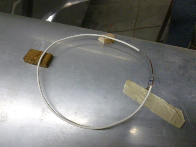
Finally got around to playing with nanoVNA and DDRR antenna.
I don't see that it can be used for a Comm antenna (118-136MHz). Too narrow bandwidth. Tried different things like changing gap, tap point, height and length. Formulas seem to be off. Found needed smaller circle (circumference). Also tap location closer to 0.5" that the 2.5 to 2.8" calculated points. I used a relatively thin wire as opposed to the recommended 1/4" to 1/2" tubing, hoping it would broaden the bandwidth (according to this remark:"The larger D is the higher efficiency is"). Bob tried to answer that for me but I'm still not sure if "efficiency" is related to bandwidth ("Q"). Perhaps I misunderstood that and should try 1/4" tubing?
[img]cid:part1.FBC49696.FA16FC0C(at)gmail.com[/img]
With a whip antenna, the bigger the diameter, the broader the bandwidth.
However, for an ELT antenna it will be perfect under engine cowling or on turtle deck. Saw SWR below 1:1.10 while fiddling with it. Some have installed their ELT antenna in their RV-4 under the canopy between pilot and passenger. Obviously without measuring SWR. A hand (much less a head or the rollover structure) severely affect SWR. Of course ground plane is very much in question in that location.
I also tried a 3/32" brass tube originating at very rear of canopy (ground contact to turtle deck) extending forward and up along the canopy. Very odd frequency response and very SWR sensitive to a hand near the tip.
At this point I'm looking at designing a streamline base for my 3/32" brass tubing in Solidworks and 3D printing it, mounting the antenna traditionally just behind the aft canopy skirt. Perhaps squeezing the tubing into a somewhat streamline and/or stepping down to 1/8" after the first 12" piece.
Finn
On 7/15/2020 11:47 PM, Robert L. Nuckolls, III wrote:
| Quote: | At 04:36 PM 7/15/2020, you wrote:
| Quote: | I ordered this https://www.ebay.com/itm/283898850600Â ten days ago. Will probably be several weeks before I get it.
You can get them a lot cheaper, but I wanted one that'll also be useful checking transponder (and ADS-B) cable and antenna. (1GHz)
Still haven't given up on the idea of putting VHF comm antenna under the RV-4 canopy. Other than vertical polarization, ground plane will probably be the biggest issue (and impedance matching if I can't get the ground plane right). Got three 12"Â 5/32"OD brass tubes from Hobby Lobby. Should give a reasonably wide bandwidth.
Finn |
Check out this article from a 1971 issue of QST Magazine
http://www.aeroelectric.com/articles/Antennas/DDRR_Antenna.PDF
A 2 meter (146 Mhz) version of this antenna
is 6" in diameter and sets about 1" off the
ground plane. An aviation version would be
about 7" in diameter.
It's bandwidth is probably pretty narrow . . .
you'd have to build one and sweep it to
see if it's usable. Would this fit on
the deck just behind the rear seat?
I've got one of those analyzers but haven't
had time to make it sing, dance and do dishes.
I've been using the VNA Tiny which is a good
bit more expensive. It seems to work well.
Let us know how that 'baby' VNA works for you!
Bob . . . |
 Virus-free. www.avast.com [url=#DAB4FAD8-2DD7-40BB-A1B8-4E2AA1F9FDF2] [/url] Virus-free. www.avast.com [url=#DAB4FAD8-2DD7-40BB-A1B8-4E2AA1F9FDF2] [/url]
| | - The Matronics AeroElectric-List Email Forum - | | | Use the List Feature Navigator to browse the many List utilities available such as the Email Subscriptions page, Archive Search & Download, 7-Day Browse, Chat, FAQ, Photoshare, and much more:
http://www.matronics.com/Navigator?AeroElectric-List |
|
| Description: |
|
| Filesize: |
150 KB |
| Viewed: |
4786 Time(s) |
|
|
|
| Back to top |
|
 |
ceengland7(at)gmail.com
Guest
|
| Posted: Sun Sep 27, 2020 4:52 pm Post subject: antenna analyzer? Antennas |
|
|
I can't imagine a smaller dia wire spreading the freq peak, but then I've never seen that style antenna, either.  Maybe 'efficiency' in this context means usability across more of the frequency spectrum (lower Q). Certainly seems worth trying with 3/8 or 1/2 tubing, or 1/2" copper tape wrapped around something. Don't know if you care, but most ELTs require using their dedicated antenna to be 'legal', somewhat analogous to the silliness in FAA rules for GPS for IFR operations. I don't worry about the FAA that much, but if you insure the plane, it could give the ins co an out after an accident. Maybe 'efficiency' in this context means usability across more of the frequency spectrum (lower Q). Certainly seems worth trying with 3/8 or 1/2 tubing, or 1/2" copper tape wrapped around something. Don't know if you care, but most ELTs require using their dedicated antenna to be 'legal', somewhat analogous to the silliness in FAA rules for GPS for IFR operations. I don't worry about the FAA that much, but if you insure the plane, it could give the ins co an out after an accident.
I assume you're using an old style 121Mhz ELT, right? The new dual freq models seem to require highly specialized antennas.
RE: brass for antenna. If you're talking about outside the canopy, you might want to re-think it. My 1st RV4 had the stainless wire whip ELT antenna mounted there, until it didn't. It broke off at the stress riser where it entered the long composite mounting cone. Behind the canopy is a really 'dirty', turbulent area. Maybe you could silver-solder a length of stainless tubing? Or 1/2" copper tape wrapped on a 'glass arrow shaft. I bet it'll still need some kind of support a few inches above the skin.
Have fun...
Charlie
On 9/27/2020 7:17 PM, Finn Lassen wrote:
| Quote: |
Finally got around to playing with nanoVNA and DDRR antenna.
I don't see that it can be used for a Comm antenna (118-136MHz). Too narrow bandwidth. Tried different things like changing gap, tap point, height and length. Formulas seem to be off. Found needed smaller circle (circumference). Also tap location closer to 0.5" that the 2.5 to 2.8" calculated points. I used a relatively thin wire as opposed to the recommended 1/4" to 1/2" tubing, hoping it would broaden the bandwidth (according to this remark:"The larger D is the higher efficiency is"). Bob tried to answer that for me but I'm still not sure if "efficiency" is related to bandwidth ("Q"). Perhaps I misunderstood that and should try 1/4" tubing?
With a whip antenna, the bigger the diameter, the broader the bandwidth.
However, for an ELT antenna it will be perfect under engine cowling or on turtle deck. Saw SWR below 1:1.10 while fiddling with it. Some have installed their ELT antenna in their RV-4 under the canopy between pilot and passenger. Obviously without measuring SWR. A hand (much less a head or the rollover structure) severely affect SWR. Of course ground plane is very much in question in that location.
I also tried a 3/32" brass tube originating at very rear of canopy (ground contact to turtle deck) extending forward and up along the canopy. Very odd frequency response and very SWR sensitive to a hand near the tip.
At this point I'm looking at designing a streamline base for my 3/32" brass tubing in Solidworks and 3D printing it, mounting the antenna traditionally just behind the aft canopy skirt. Perhaps squeezing the tubing into a somewhat streamline and/or stepping down to 1/8" after the first 12" piece.
Finn
On 7/15/2020 11:47 PM, Robert L. Nuckolls, III wrote:
| Quote: | At 04:36 PM 7/15/2020, you wrote:
| Quote: | I ordered this https://www.ebay.com/itm/283898850600Â ten days ago. Will probably be several weeks before I get it.
You can get them a lot cheaper, but I wanted one that'll also be useful checking transponder (and ADS-B) cable and antenna. (1GHz)
Still haven't given up on the idea of putting VHF comm antenna under the RV-4 canopy. Other than vertical polarization, ground plane will probably be the biggest issue (and impedance matching if I can't get the ground plane right). Got three 12"Â 5/32"OD brass tubes from Hobby Lobby. Should give a reasonably wide bandwidth.
Finn |
Check out this article from a 1971 issue of QST Magazine
http://www.aeroelectric.com/articles/Antennas/DDRR_Antenna.PDF
A 2 meter (146 Mhz) version of this antenna
is 6" in diameter and sets about 1" off the
ground plane. An aviation version would be
about 7" in diameter.
It's bandwidth is probably pretty narrow . . .
you'd have to build one and sweep it to
see if it's usable. Would this fit on
the deck just behind the rear seat?
I've got one of those analyzers but haven't
had time to make it sing, dance and do dishes.
I've been using the VNA Tiny which is a good
bit more expensive. It seems to work well.
Let us know how that 'baby' VNA works for you!
Bob . . . |
Virus-free. www.avast.com [url=#DAB4FAD8-2DD7-40BB-A1B8-4E2AA1F9FDF2] [/url]
|
| | - The Matronics AeroElectric-List Email Forum - | | | Use the List Feature Navigator to browse the many List utilities available such as the Email Subscriptions page, Archive Search & Download, 7-Day Browse, Chat, FAQ, Photoshare, and much more:
http://www.matronics.com/Navigator?AeroElectric-List |
|
|
|
| Back to top |
|
|
nuckolls.bob(at)aeroelect
Guest
|
| Posted: Sun Sep 27, 2020 5:26 pm Post subject: antenna analyzer? Antennas |
|
|
| Quote: | I used a relatively thin wire as opposed to the recommended 1/4"
to 1/2" tubing, hoping it would broaden the bandwidth (according to
this remark:"The larger D is the higher efficiency is").
Bob tried to answer that for me but I'm still not sure if
"efficiency" is related to bandwidth ("Q").
Perhaps I misunderstood that and should try 1/4" tubing? |
Or even a radiator fabricated from flat sheet?
The larger the diameter, the greater the bandwidth.
Efficiency has to do with ohmic losses (how much
energy goes off in heat) and again, a larger surface
area of the radiator has lower resistance. Recall that
currents at these frequencies flow on the skin
of the conductor. At DC, there is a substantial
difference between say a 1" diameter rod and a 1"
thin wall tube. At 100 MHz there is virtually
no difference 'cause all the 'happening' is at
the surface.
| Quote: | With a whip antenna, the bigger the diameter, the broader the bandwidth.
|
Exactly . . .
| Quote: | I also tried a 3/32" brass tube originating at very rear of canopy (ground contact to turtle deck) extending forward and up along the canopy. Very odd frequency response and very SWR sensitive to a hand near the tip.
|
Interesting observation . . .
| Quote: | | At this point I'm looking at designing a streamline base for my 3/32" brass tubing in Solidworks and 3D printing it, mounting the antenna traditionally just behind the aft canopy skirt. Perhaps squeezing the tubing into a somewhat streamline and/or stepping down to 1/8" after the first 12" piece. |
Also interesting . . . let us know
what you discover.
I am pleased that you've availed yourself
of this unusual piece of test equipment. You're
gaining knowledge and experience in a manner
that you will not forget . . . and will become
valuable information source for those who
follow.
Bob . . .
| | - The Matronics AeroElectric-List Email Forum - | | | Use the List Feature Navigator to browse the many List utilities available such as the Email Subscriptions page, Archive Search & Download, 7-Day Browse, Chat, FAQ, Photoshare, and much more:
http://www.matronics.com/Navigator?AeroElectric-List |
|
|
|
| Back to top |
|
|
finn.usa(at)gmail.com
Guest
|
| Posted: Mon Sep 28, 2020 5:43 am Post subject: antenna analyzer? Antennas |
|
|
I guess ideally a tapered carbonfiber tube (perhaps wrapped with copper
table within another tapered carbonfiber tube).
I wonder if the carbon material is conductive enough for our purposes.
Finn
On 9/27/2020 8:51 PM, Charlie England wrote:
| Quote: | RE: brass for antenna. If you're talking about outside the canopy, you
might want to re-think it. My 1st RV4 had the stainless wire whip ELT
antenna mounted there, until it didn't. It broke off at the stress
riser where it entered the long composite mounting cone. Behind the
canopy is a really 'dirty', turbulent area. Maybe you could
silver-solder a length of stainless tubing? Or 1/2" copper tape
wrapped on a 'glass arrow shaft. I bet it'll still need some kind of
support a few inches above the skin.
|
---
This email has been checked for viruses by Avast antivirus software.
https://www.avast.com/antivirus
| | - The Matronics AeroElectric-List Email Forum - | | | Use the List Feature Navigator to browse the many List utilities available such as the Email Subscriptions page, Archive Search & Download, 7-Day Browse, Chat, FAQ, Photoshare, and much more:
http://www.matronics.com/Navigator?AeroElectric-List |
|
|
|
| Back to top |
|
|
nuckolls.bob(at)aeroelect
Guest
|
| Posted: Mon Sep 28, 2020 6:59 am Post subject: antenna analyzer? Antennas |
|
|
At 08:43 AM 9/28/2020, you wrote:
| Quote: | --> AeroElectric-List message posted by: Finn Lassen <finn.usa(at)gmail.com>
I guess ideally a tapered carbonfiber tube (perhaps wrapped with copper table within another tapered carbonfiber tube).
|
Can you easily conduct the experiment? Sounds
interesting.
| Quote: | | I wonder if the carbon material is conductive enough for our purposes. |
No. Antennas on our carbon aircraft at Hawker-Beech
required a beefed up ground plane. We also had to add
a distributed ground system for electrics . . . super pain
in the you know what . . .
Bob . . .
| | - The Matronics AeroElectric-List Email Forum - | | | Use the List Feature Navigator to browse the many List utilities available such as the Email Subscriptions page, Archive Search & Download, 7-Day Browse, Chat, FAQ, Photoshare, and much more:
http://www.matronics.com/Navigator?AeroElectric-List |
|
|
|
| Back to top |
|
|
finn.usa(at)gmail.com
Guest
|
| Posted: Mon Sep 28, 2020 11:54 am Post subject: antenna analyzer? Antennas |
|
|
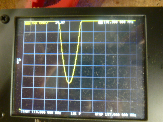
Tried with bigger "tubing" (Did not want to spend $ and time going to local hardware store to pick up 1/2" soft copper tubing and elbow.)
Size of wire or tubing does not appear to influence bandwidth.
So, my conclusion is unchanged: good compact vertically polarized antenna for single-frequency use, like ELT or 144-146MHz "band".
Not usable as wideband antenna. 118-136MHz certainly is wideband. (18/127 = 14%).
Would love to have someone else experiment with it and see if they somehow could get 1:3 SWR over 118-136MHz.
[img]cid:part1.9223A322.93ACD30A(at)gmail.com[/img]
[img]cid:part2.B888D8DB.B870AD98(at)gmail.com[/img]
118-137MHz, 1:4 SWR at top.
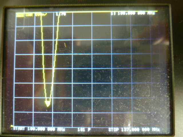
[img]cid:part3.AC576CD0.797E1988(at)gmail.com[/img]
[img]cid:part4.2F227B3F.402B8D8D(at)gmail.com[/img]
100-137MHz, 1:4 SWR at top.
You can definitely tune it to much better SWR at center frequency, but that was not the purpose here.
Finn
On 9/27/2020 9:24 PM, Robert L. Nuckolls, III wrote:
| Quote: | | Quote: | I used a relatively thin wire as opposed to the recommended 1/4"
to 1/2" tubing, hoping it would broaden the bandwidth (according to
this remark:"The larger D is the higher efficiency is").
Bob tried to answer that for me but I'm still not sure if
"efficiency" is related to bandwidth ("Q").
Perhaps I misunderstood that and should try 1/4" tubing? |
Or even a radiator fabricated from flat sheet?
The larger the diameter, the greater the bandwidth.
Efficiency has to do with ohmic losses (how much
energy goes off in heat) and again, a larger surface
area of the radiator has lower resistance. Recall that
currents at these frequencies flow on the skin
of the conductor. At DC, there is a substantial
difference between say a 1" diameter rod and a 1"
thin wall tube. At 100 MHz there is virtually
no difference 'cause all the 'happening' is at
the surface.
| Quote: | With a whip antenna, the bigger the diameter, the broader the bandwidth.
|
Exactly . . .
| Quote: | I also tried a 3/32" brass tube originating at very rear of canopy (ground contact to turtle deck) extending forward and up along the canopy. Very odd frequency response and very SWR sensitive to a hand near the tip.
|
Interesting observation . . .
| Quote: | | At this point I'm looking at designing a streamline base for my 3/32" brass tubing in Solidworks and 3D printing it, mounting the antenna traditionally just behind the aft canopy skirt. Perhaps squeezing the tubing into a somewhat streamline and/or stepping down to 1/8" after the first 12" piece. |
Also interesting . . . let us know
what you discover.
I am pleased that you've availed yourself
of this unusual piece of test equipment. You're
gaining knowledge and experience in a manner
that you will not forget . . . and will become
valuable information source for those who
follow.
Bob . . . |
Virus-free. www.avast.com [url=#DAB4FAD8-2DD7-40BB-A1B8-4E2AA1F9FDF2] [/url]
| | - The Matronics AeroElectric-List Email Forum - | | | Use the List Feature Navigator to browse the many List utilities available such as the Email Subscriptions page, Archive Search & Download, 7-Day Browse, Chat, FAQ, Photoshare, and much more:
http://www.matronics.com/Navigator?AeroElectric-List |
|
| Description: |
|
| Filesize: |
161 KB |
| Viewed: |
4773 Time(s) |

|
| Description: |
|
| Filesize: |
154.5 KB |
| Viewed: |
4773 Time(s) |
|
| Description: |
|
| Filesize: |
157 KB |
| Viewed: |
4773 Time(s) |

|
| Description: |
|
| Filesize: |
143 KB |
| Viewed: |
4773 Time(s) |
|
|
|
| Back to top |
|
|
nuckolls.bob(at)aeroelect
Guest
|
| Posted: Wed Sep 30, 2020 1:07 pm Post subject: antenna analyzer? Antennas |
|
|
| Quote: |
Would love to have someone else experiment with it and see if they somehow could get 1:3 SWR over 118-136MHz.
|
It's been some years since I built one of these
(back in the days before vna's) and a similar
interval since I reviewed the literature.
Poked around on the 'net and my archives a bit
and I think I can confidently offer an explanation
for the fruitlessness of your endeavors.
The DDRR is a vertically polarized antenna wherein
the very short vertical mast is the radiator.
All that other stuff is a loading reactance for
the antenna . . . or 'top hat' in some circles.
Given that the radiation from an antenna is
proportional to the current flowing in the radiator
then it follows that this diminutive antenna
must have some bodacious currents. Further, where
the currents are high, losses need to be low
to minimize energy lost to heating.
My assertion about larger diameters improving
bandwidth was incorrectly applied to this
discussion. L/d ratio as it goes to bandwidth
works only in the resonant radiating portions of the
antenna . . . in this case, the mast. All
that stuff setting on top has a rapidly
diminishing current flow and besides, that
part doesn't radiate.
More surface area (diameter) helps this antenna
only in the radiator . . . the mast supporting
the top hat. Increasing surface area in the loading
portion goes to increased Q which means narrower
bandwidth.
The governing triad is profoundly demonstrated
in the magnetic loop antennas used on the HF
ham bands. There are very useful loop antennas crafted
for the 80M (3.5 to 4.0 Mhz) ham band where
the radiator is built from 1-2" copper pipe with
soldered joints in 45 degree elbows employed
to make an 8-sided 'circle'. The Q of these
antennas is very high which means hi currents
at the feedpoint, high voltages at the tuning
gap. The bandwidth of these antennas is very
narrow. The operator has to tune the antenna
in lockstep with his transceiver in order to
'cruise' that band for contacts.
http://www.oh2gqc.com/wp-content/uploads/2017/09/20170911_160930.jpg
Several sages in the design and fabrication
of antennas have noted, "one can strive for
(1) efficiency, (2) size and/or (3) bandwidth
with one overpowering caveat. Optimizing any two
qualities calls for degrading the third. So pick
two goals and live with consequences for the
third."
Therefore, your experience with the DDRR was
predictable. Yeah, you can get a really useful,
small profile antenna but because SIZE was
diminished, bandwidth suffers.
I thank you for sharing the results of your
experiment.
Bob . . .
| | - The Matronics AeroElectric-List Email Forum - | | | Use the List Feature Navigator to browse the many List utilities available such as the Email Subscriptions page, Archive Search & Download, 7-Day Browse, Chat, FAQ, Photoshare, and much more:
http://www.matronics.com/Navigator?AeroElectric-List |
|
|
|
| Back to top |
|
|
finn.usa(at)gmail.com
Guest
|
| Posted: Wed Sep 30, 2020 2:36 pm Post subject: antenna analyzer? Antennas |
|
|
"mast" Coax to ring or ring to ground plane?
So increasing ring to ground plane to a maybe 3/4" piece of tubing would increase bandwidth?
But probably not significantly enough to say 1:3 SWR over the 188-136MHz band?
Finn
On 9/30/2020 5:04 PM, Robert L. Nuckolls, III wrote:
| Quote: | | Quote: |
Would love to have someone else experiment with it and see if they somehow could get 1:3 SWR over 118-136MHz.
|
It's been some years since I built one of these
(back in the days before vna's) and a similar
interval since I reviewed the literature.
Poked around on the 'net and my archives a bit
and I think I can confidently offer an explanation
for the fruitlessness of your endeavors.
The DDRR is a vertically polarized antenna wherein
the very short vertical mast is the radiator.
All that other stuff is a loading reactance for
the antenna . . . or 'top hat' in some circles.
Given that the radiation from an antenna is
proportional to the current flowing in the radiator
then it follows that this diminutive antenna
must have some bodacious currents. Further, where
the currents are high, losses need to be low
to minimize energy lost to heating.
My assertion about larger diameters improving
bandwidth was incorrectly applied to this
discussion. L/d ratio as it goes to bandwidth
works only in the resonant radiating portions of the
antenna . . . in this case, the mast. All
that stuff setting on top has a rapidly
diminishing current flow and besides, that
part doesn't radiate.
More surface area (diameter) helps this antenna
only in the radiator . . . the mast supporting
the top hat. Increasing surface area in the loading
portion goes to increased Q which means narrower
bandwidth.
The governing triad is profoundly demonstrated
in the magnetic loop antennas used on the HF
ham bands. There are very useful loop antennas crafted
for the 80M (3.5 to 4.0 Mhz) ham band where
the radiator is built from 1-2" copper pipe with
soldered joints in 45 degree elbows employed
to make an 8-sided 'circle'. The Q of these
antennas is very high which means hi currents
at the feedpoint, high voltages at the tuning
gap. The bandwidth of these antennas is very
narrow. The operator has to tune the antenna
in lockstep with his transceiver in order to
'cruise' that band for contacts.
http://www.oh2gqc.com/wp-content/uploads/2017/09/20170911_160930.jpg
Several sages in the design and fabrication
of antennas have noted, "one can strive for
(1) efficiency, (2) size and/or (3) bandwidth
with one overpowering caveat. Optimizing any two
qualities calls for degrading the third. So pick
two goals and live with consequences for the
third."
Therefore, your experience with the DDRR was
predictable. Yeah, you can get a really useful,
small profile antenna but because SIZE was
diminished, bandwidth suffers.
I thank you for sharing the results of your
experiment.
Bob . . . |
Virus-free. www.avast.com [url=#DAB4FAD8-2DD7-40BB-A1B8-4E2AA1F9FDF2] [/url]
| | - The Matronics AeroElectric-List Email Forum - | | | Use the List Feature Navigator to browse the many List utilities available such as the Email Subscriptions page, Archive Search & Download, 7-Day Browse, Chat, FAQ, Photoshare, and much more:
http://www.matronics.com/Navigator?AeroElectric-List |
|
|
|
| Back to top |
|
|
nuckolls.bob(at)aeroelect
Guest
|
| Posted: Wed Sep 30, 2020 4:30 pm Post subject: antenna analyzer? Antennas |
|
|
At 05:33 PM 9/30/2020, you wrote:
| Quote: | | "mast" Coax to ring or ring to ground plane? |
the ring to ground plane . . .
| Quote: | | So increasing ring to ground plane to a maybe 3/4" piece of tubing would increase bandwidth? |
no . . . that radiator is a fraction of a wavelength.
It resonates based on the reactive (capacitive)
effects of the ring.
| Quote: | | But probably not significantly enough to say 1:3 SWR over the 118-136MHz band? |
Interesting experiement . . . it might get
wider but probably way short of design
goals.
| Quote: | Finn
On 9/30/2020 5:04 PM, Robert L. Nuckolls, III wrote:
| Quote: | | Quote: |
Would love to have someone else experiment with it and see if they somehow could get 1:3 SWR over 118-136MHz. |
It's been some years since I built one of these
(back in the days before vna's) and a similar
interval since I reviewed the literature.
Poked around on the 'net and my archives a bit
and I think I can confidently offer an explanation
for the fruitlessness of your endeavors.
The DDRR is a vertically polarized antenna wherein
the very short vertical mast is the radiator.
All that other stuff is a loading reactance for
the antenna . . . or 'top hat' in some circles.
Given that the radiation from an antenna is
proportional to the current flowing in the radiator
then it follows that this diminutive antenna
must have some bodacious currents. Further, where
the currents are high, losses need to be low
to minimize energy lost to heating.
My assertion about larger diameters improving
bandwidth was incorrectly applied to this
discussion. L/d ratio as it goes to bandwidth
works only in the resonant radiating portions of the
antenna . . . in this case, the mast. All
that stuff setting on top has a rapidly
diminishing current flow and besides, that
part doesn't radiate.
More surface area (diameter) helps this antenna
only in the radiator . . . the mast supporting
the top hat. Increasing surface area in the loading
portion goes to increased Q which means narrower
bandwidth.
The governing triad is profoundly demonstrated
in the magnetic loop antennas used on the HF
ham bands. There are very useful loop antennas crafted
for the 80M (3.5 to 4.0 Mhz) ham band where
the radiator is built from 1-2" copper pipe with
soldered joints in 45 degree elbows employed
to make an 8-sided 'circle'. The Q of these
antennas is very high which means hi currents
at the feedpoint, high voltages at the tuning
gap. The bandwidth of these antennas is very
narrow. The operator has to tune the antenna
in lockstep with his transceiver in order to
'cruise' that band for contacts.
http://www.oh2gqc.com/wp-content/uploads/2017/09/20170911_160930.jpg
Several sages in the design and fabrication
of antennas have noted, "one can strive for
(1) efficiency, (2) size and/or (3) bandwidth
with one overpowering caveat. Optimizing any two
qualities calls for degrading the third. So pick
two goals and live with consequences for the
third."
Therefore, your experience with the DDRR was
predictable. Yeah, you can get a really useful,
small profile antenna but because SIZE was
diminished, bandwidth suffers.
I thank you for sharing the results of your
experiment.
Bob . . . |
Virus-free. www.avast.com[url=#DAB4FAD8-2DD7-40BB-A1B8-4E2AA1F9FDF2] [/url] |
Bob . . .
| | - The Matronics AeroElectric-List Email Forum - | | | Use the List Feature Navigator to browse the many List utilities available such as the Email Subscriptions page, Archive Search & Download, 7-Day Browse, Chat, FAQ, Photoshare, and much more:
http://www.matronics.com/Navigator?AeroElectric-List |
|
|
|
| Back to top |
|
|
ceengland7(at)gmail.com
Guest
|
| Posted: Wed Sep 30, 2020 5:35 pm Post subject: antenna analyzer? Antennas |
|
|
I did a bit of web browsing on the DDRR. This thread is about a 2 meter version (above our comm band):
https://forums.qrz.com/index.php?threads/2m-ddrr-antenna-for-vehicle-some-questions.368057/
The thread contains this sentence:
"The DDRR is an inverted-L. A 3" tall, 146 MHz DDRR has a radiation resistance of 3.0 ohms. The 2:1 VSWR bandwidth is 1.5 MHz."
On 9/30/2020 7:27 PM, Robert L. Nuckolls, III wrote:
| Quote: | At 05:33 PM 9/30/2020, you wrote:
| Quote: | | "mast" Coax to ring or ring to ground plane? |
the ring to ground plane . . .
| Quote: | | So increasing ring to ground plane to a maybe 3/4" piece of tubing would increase bandwidth? |
no . . . that radiator is a fraction of a wavelength.
It resonates based on the reactive (capacitive)
effects of the ring.
| Quote: | | But probably not significantly enough to say 1:3 SWR over the 118-136MHz band? |
Interesting experiement . . . it might get
wider but probably way short of design
goals.
| Quote: | Finn
On 9/30/2020 5:04 PM, Robert L. Nuckolls, III wrote:
| Quote: | | Quote: |
Would love to have someone else experiment with it and see if they somehow could get 1:3 SWR over 118-136MHz. |
It's been some years since I built one of these
(back in the days before vna's) and a similar
interval since I reviewed the literature.
Poked around on the 'net and my archives a bit
and I think I can confidently offer an explanation
for the fruitlessness of your endeavors.
The DDRR is a vertically polarized antenna wherein
the very short vertical mast is the radiator.
All that other stuff is a loading reactance for
the antenna . . . or 'top hat' in some circles.
Given that the radiation from an antenna is
proportional to the current flowing in the radiator
then it follows that this diminutive antenna
must have some bodacious currents. Further, where
the currents are high, losses need to be low
to minimize energy lost to heating.
My assertion about larger diameters improving
bandwidth was incorrectly applied to this
discussion. L/d ratio as it goes to bandwidth
works only in the resonant radiating portions of the
antenna . . . in this case, the mast. All
that stuff setting on top has a rapidly
diminishing current flow and besides, that
part doesn't radiate.
More surface area (diameter) helps this antenna
only in the radiator . . . the mast supporting
the top hat. Increasing surface area in the loading
portion goes to increased Q which means narrower
bandwidth.
The governing triad is profoundly demonstrated
in the magnetic loop antennas used on the HF
ham bands. There are very useful loop antennas crafted
for the 80M (3.5 to 4.0 Mhz) ham band where
the radiator is built from 1-2" copper pipe with
soldered joints in 45 degree elbows employed
to make an 8-sided 'circle'. The Q of these
antennas is very high which means hi currents
at the feedpoint, high voltages at the tuning
gap. The bandwidth of these antennas is very
narrow. The operator has to tune the antenna
in lockstep with his transceiver in order to
'cruise' that band for contacts.
http://www.oh2gqc.com/wp-content/uploads/2017/09/20170911_160930.jpg
Several sages in the design and fabrication
of antennas have noted, "one can strive for
(1) efficiency, (2) size and/or (3) bandwidth
with one overpowering caveat. Optimizing any two
qualities calls for degrading the third. So pick
two goals and live with consequences for the
third."
Therefore, your experience with the DDRR was
predictable. Yeah, you can get a really useful,
small profile antenna but because SIZE was
diminished, bandwidth suffers.
I thank you for sharing the results of your
experiment.
Bob . . . |
Virus-free. www.avast.com[url=#DAB4FAD8-2DD7-40BB-A1B8-4E2AA1F9FDF2] [/url] |
Bob . . . |
| | - The Matronics AeroElectric-List Email Forum - | | | Use the List Feature Navigator to browse the many List utilities available such as the Email Subscriptions page, Archive Search & Download, 7-Day Browse, Chat, FAQ, Photoshare, and much more:
http://www.matronics.com/Navigator?AeroElectric-List |
|
|
|
| Back to top |
|
|
nuckolls.bob(at)aeroelect
Guest
|
| Posted: Thu Oct 01, 2020 5:05 am Post subject: antenna analyzer? Antennas |
|
|
At 08:32 PM 9/30/2020, you wrote:
Fairly typical. Radiator height is 3/21 or 15% of the
full size 1/4 wave. They cited a vswr 2:1 bandwidth
of 1.5/146 or 1% . . . 3:1 would be a bit wider
but still far short of that necessary for our
VHF comm bandwidths.
I'm still thinking I'd like to build one for our
local fire/ems services where 1% bandwidth is
plenty. The thing could reside under a plastic
radome and sit on a dedicated ground plane held
to the vehicle with magnets in each corner. Just
one of many PITS (pie-in-the-sky) projects in
someday bucket.
This still doesn't solve Finn's problem.
Remind me sir, what airplane are we talking
about?
Bob . . .
| | - The Matronics AeroElectric-List Email Forum - | | | Use the List Feature Navigator to browse the many List utilities available such as the Email Subscriptions page, Archive Search & Download, 7-Day Browse, Chat, FAQ, Photoshare, and much more:
http://www.matronics.com/Navigator?AeroElectric-List |
|
|
|
| Back to top |
|
|
Eric Page
Joined: 15 Feb 2017
Posts: 243
|
| Posted: Thu Oct 01, 2020 8:52 pm Post subject: Re: antenna analyzer? Antennas |
|
|
Perhaps not helpful to the antenna design y'all are pursuing in this thread, but I came across this paper today...


http://www.jpier.org/PIERM/pierm78/11.18102701.pdf


...thanks to the guys at DarkAero...


https://www.darkaero.com/


...who are experimenting with this antenna for their all-carbon fiber aircraft.


The paper describes an interesting printed circuit board antenna of meandering design.  It looks very useful for builders looking to avoid long external antennae, and if the bandwidth shown for a ~160MHz design can be duplicated at ~120MHz, it should work well.


Eric
| | - The Matronics AeroElectric-List Email Forum - | | | Use the List Feature Navigator to browse the many List utilities available such as the Email Subscriptions page, Archive Search & Download, 7-Day Browse, Chat, FAQ, Photoshare, and much more:
http://www.matronics.com/Navigator?AeroElectric-List |
|
|
|
| Back to top |
|
|
hairy_kiwi
Joined: 16 Sep 2018
Posts: 2
Location: Ledbury, UK
|
| Posted: Thu Oct 08, 2020 4:53 am Post subject: Re: antenna analyzer? Antennas |
|
|
Hi Group,
Long time lurker here. Hopefully, as the OP made the title rather broadband  a general discussion on aviation / aircraft antenna design and using antenna analyzers for verifying experiments is welcome here. Otherwise, apologies for further dragging the discussion away from the otherwise fascinating DDRR antenna design... a general discussion on aviation / aircraft antenna design and using antenna analyzers for verifying experiments is welcome here. Otherwise, apologies for further dragging the discussion away from the otherwise fascinating DDRR antenna design...
I recently bought a Rig Expert AA 230 ZOOM analyzer, primarily for helping to diagnose faults in antenna coax while doing the odd bit of experimental aircraft rewiring. Its been a great tool for quickly and easily finding poorly made BNC terminations for example (wire disconnected from center pin in a poorly made, screw-together style BNC connector) and checking SWR in a comm antenna epoxied into a composite aircraft is still acceptable years after construction.
As for using an analyzer for antenna design, the interesting, very detailed paper Eric posted a link to, titled 'Airborne VHF Printed Monopole Antenna for Platform Constrained Applications' looks like it could be a fun design to experiment with - possibly for installing inside the fin of the Kitfox I'm going to be building - especially as the ground plane is incorporated in the same plane as the antenna.
I have a basic understanding of antenna design, but its very basic - and with a few antenna issues and projects on the go, I'd be very interested in furthering my knowledge and doing some experimenting with the aid of the analyzer. What would be useful are some links to modern literature on aviation/aircraft antenna design - many thanks Eric for your post!
I had a browse through the ARRL Antenna Book which is a great tome of info, however the vast majority of that material is aimed at ground station antennas. So I'm still unclear on such things as by how much proximity to The Earth the SWR of an aircraft (comm) antennas is affected. Maybe a flight vs ground test comparison using an analyzer might be interesting to conduct, even if it proves 'no significant difference', particularly for 1/2 wave dipoles fitted internally to composite aircraft.
I've found some other recently published and interesting material with test results on (ground based) 2m 1/2 wave dipole designs that might be worth experimenting / adapting for aircraft use, but will save that for another post if there's interest.
Cheers,
Jim
Hamish 'Jim' Mead
Ledbury, UK
| | - The Matronics AeroElectric-List Email Forum - | | | Use the List Feature Navigator to browse the many List utilities available such as the Email Subscriptions page, Archive Search & Download, 7-Day Browse, Chat, FAQ, Photoshare, and much more:
http://www.matronics.com/Navigator?AeroElectric-List |
|
|
|
| Back to top |
|
|
nuckolls.bob(at)aeroelect
Guest
|
| Posted: Thu Oct 08, 2020 11:45 am Post subject: antenna analyzer? Antennas |
|
|
At 07:53 AM 10/8/2020, you wrote:

 --> AeroElectric-List message posted by: "hairy_kiwi" <hamish.mead(at)gmail.com>


 Hi Group,


 Long time lurker here. Hopefully, as the OP made the

 title rather broadband   a general discussion on

 aviation / aircraft antenna design and using antenna

 analyzers for verifying experiments is welcome here.

 Otherwise, apologies for further dragging the discussion

 away from the otherwise fascinating DDRR antenna design...


   I think we're done with the DDRR for now.

   It seems unlikely that a satisfactory fabrication

   technique for increasing bandwidth will be

   forthcoming.


   The antenna gurus all seem to agree that the

   perfect triad of size, efficency and bandwidth

   is like finding a way to to resolve cube roots

   with a pencil/paper. Unfortunately for the DDRR, the

   primary driver (size) put the kibosh on at least

   one of the other two, mainly bandwidth.


 I recently bought a Rig Expert AA 230 ZOOM analyzer,

   <snip>


   I've seen those tools on the web . . . they seem

   widely utilized with satisfaction.


 As for using an analyzer for antenna design, the interesting, very detailed paper Eric posted a link to, titled 'Airborne VHF Printed Monopole Antenna for Platform Constrained Applications' looks like it could be a fun design to experiment with - possibly for installing inside the fin of the Kitfox I'm going to be building - especially as the ground plane is incorporated in the same plane as the antenna.


   On page 2 we find this statement, "The major constraint

   in designing an airborne printed monopole antenna

   in VHF/UHF band is achieving compactness and wide

   bandwidth simultaneously, along with sufficient gain."


   This assertion pays homage to the SEB triad with

   the operative phrase being "sufficient gain".


   Figure 6 shows that a very satisfactory bandwidth

   was achieved while Figure 7 shows the sacrifices in

   efficiency wherein the two test conditions demonstrate

   losses of 6 to 15 dB over the bandwidth of interest.


   That's 1/4 to 1/32 of the radiated energy offered

   by the reference antenna. Sufficient? Maybe. Recall

   that all VHF comm is line of sight . . . you don't

   talk past the horizon and in any case, it's almost

   never necessary to have conversation beyond 50

   miles or so. So maybe, just maybe an antenna with

   that efficiency profile would provide satisfactory

   communications for some if not all builders.


   The proof is in the pudding (I prefer vanilla-tapicoa

   myself).


 I had a browse through the ARRL Antenna Book which is a great tome of info, however the vast majority of that material is aimed at ground station antennas. So I'm still unclear on such things as by how much proximity to The Earth the SWR of an aircraft (comm) antennas is affected.


   It's not . . . but proximity to conducting aircraft

   structure (artificial ground) is.  So ground vs.

   airborne testing is probably not useful.


   The flight test of intense interest would be with

   perhaps a software driven receiver (SDR) on board

   where you would fly 360s out 40 miles or so from a handy

   ground station and plot comparative azimuth measurements of your

   test antenna with respect to a more conventional vhf comm

   whip.  We used to do a good bit of this type testing

   at Hawer-Beech . . . which requires another previously

   expensive but now not so much spectrum analyzer/receiver

   with signal strength display.


 I've found some other recently published and interesting material with test results on (ground based) 2m 1/2 wave dipole designs that might be worth experimenting / adapting for aircraft use, but will save that for another post if there's interest.


   Let's look at them . . .


   Bob . . .
| | - The Matronics AeroElectric-List Email Forum - | | | Use the List Feature Navigator to browse the many List utilities available such as the Email Subscriptions page, Archive Search & Download, 7-Day Browse, Chat, FAQ, Photoshare, and much more:
http://www.matronics.com/Navigator?AeroElectric-List |
|
|
|
| Back to top |
|
|
|
|
You cannot post new topics in this forum
You cannot reply to topics in this forum
You cannot edit your posts in this forum
You cannot delete your posts in this forum
You cannot vote in polls in this forum
You cannot attach files in this forum
You can download files in this forum
|
Powered by phpBB © 2001, 2005 phpBB Group
|

