 |
Matronics Email Lists
Web Forum Interface to the Matronics Email Lists
|
| View previous topic :: View next topic |
| Author |
Message |
supik
Joined: 22 Aug 2018
Posts: 70
|
 Posted: Fri Jun 26, 2020 2:56 pm Post subject: RV10 Single Batt + Dual Alternator Posted: Fri Jun 26, 2020 2:56 pm Post subject: RV10 Single Batt + Dual Alternator |
 |
|
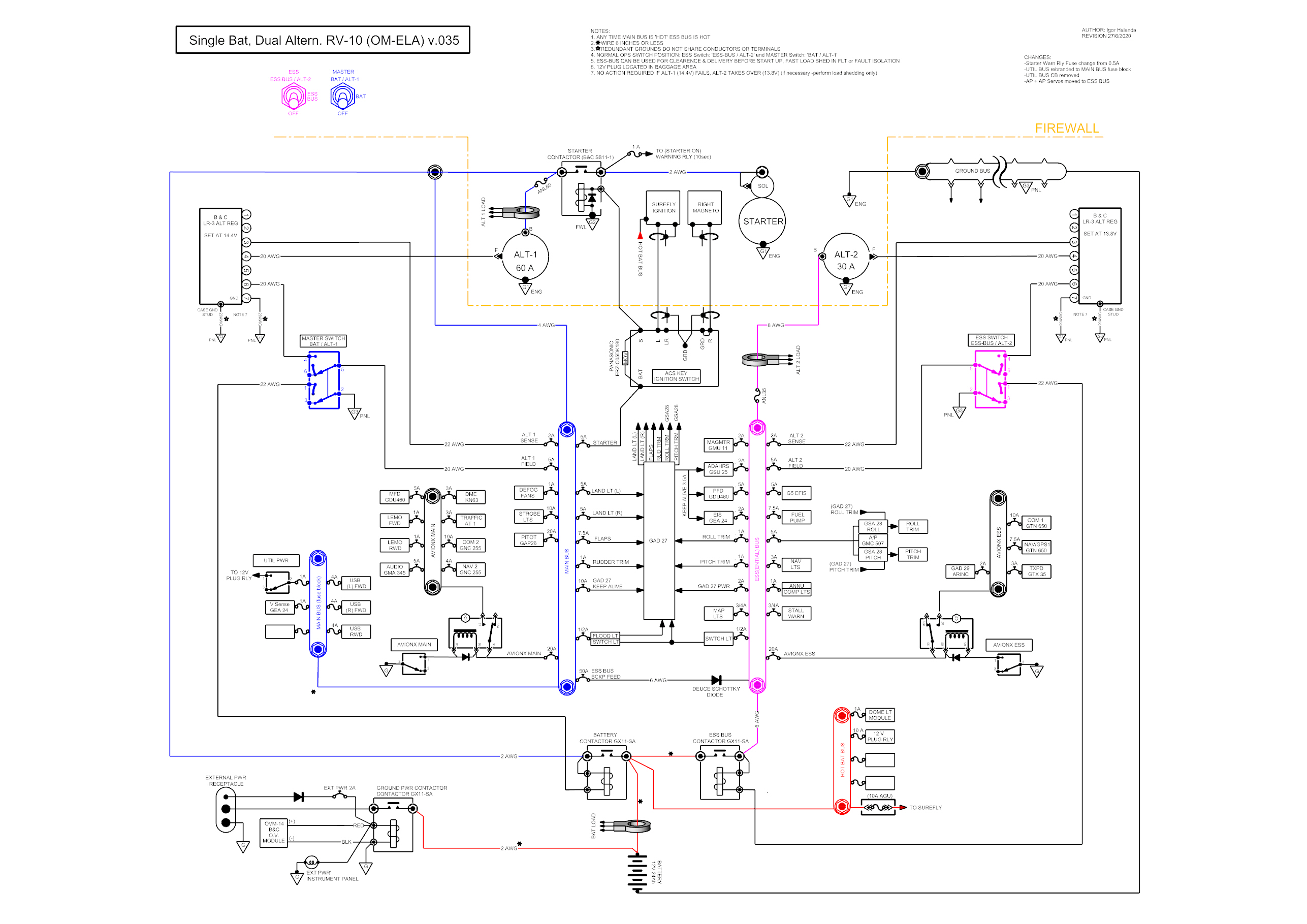
I think I am somehow close to the Z101. As the batt in the RV10 is located in the tailcone -with the ALT-2 connected to the ESS bus I tried to avoid the long always hot wire between the BATT and ALT-2 B lead.


ESS BUS switch with ALT-2 is normally ON during normal flight. ALT-2 is set at lower voltage vs. ALT-1


I know I'll get crucified for the 2 AVIONICS BUSES..I plan to move the autopilot and its servos from the AVIONX ESS bus to the ESS BUS to avoid inductive loads on the AVIONX ESS bus.


The 50amp CB between the MAIN BUS and ESS BUS is there to protect the diode and possibly isolate the MAIN BUS if ESS BUS develops a hard fault.


Do you see any other potential NO GO issues with this setup or is it acceptable?


https://i.ibb.co/NmqVgWx/Diagram-OM-ELA-Igor-v-034.jpg
| | - The Matronics AeroElectric-List Email Forum - | | | Use the List Feature Navigator to browse the many List utilities available such as the Email Subscriptions page, Archive Search & Download, 7-Day Browse, Chat, FAQ, Photoshare, and much more:
http://www.matronics.com/Navigator?AeroElectric-List |
|
_________________
Igor
RV10 in progress
Last edited by supik on Tue Jun 30, 2020 4:34 am; edited 1 time in total |
|
| Back to top |
|
 |
user9253
Joined: 28 Mar 2008
Posts: 1908
Location: Riley TWP Michigan
|
| Posted: Fri Jun 26, 2020 5:17 pm Post subject: Re: RV10 Single Batt + Dual Alternator |
|
|
The schematic diagram is overly complicated.

The utility bus can be eliminated and those loads can be powered directly from the Main power bus.

Both avionics buses can be eliminated and those loads can be powered directly from the Essential bus.

The two alternators will be connected in parallel whenever both contactors are energized.

Is one of the alternators set at a lower output voltage than the other one?

The two relays are unnecessary failure points.

Eventually some other pilot will fly your plane.

Will that pilot know what to do  when some component fails?
| | - The Matronics AeroElectric-List Email Forum - | | | Use the List Feature Navigator to browse the many List utilities available such as the Email Subscriptions page, Archive Search & Download, 7-Day Browse, Chat, FAQ, Photoshare, and much more:
http://www.matronics.com/Navigator?AeroElectric-List |
|
_________________
Joe Gores |
|
| Back to top |
|
|
bobmeyers
Joined: 05 May 2017
Posts: 4
|
| Posted: Sat Jun 27, 2020 7:02 am Post subject: Re: RV10 Single Batt + Dual Alternator |
|
|
I would rethink what you are trying to accomplish.


With all the monkey motion going on, it would seem you would be better served  going with a Z-14 rather than a gummed up Z-101.


Why an avionic bus at all let alone two? I would kill them both and their relays.


A utility bus seems way over the top. If you wish to control a utility device just have a power switch for that device co-located with it. I would kill the utility bus


If the motivation for the avionic buses is to avoid brown out of all the avionic devices not on the GAD 27, a Z-14 system will solve that for you. Most of the Garmin devices have a second power input you can connect to a second bus. You can use a bridge rectifier to enable dual power feeds to any device that only has one power input.


When I wired my RV14 I first drew up something similar to the ideas behind Z-101. If the current Z-101 had been around I may have been more confident in using that kind of layout. I went with a Z-14 layout instead.


When I get in my plane, I turn on batt 2 and all the avionics come up and stay up. I turn on batt 1 as part of my startup checklist. During engine start, no brown outs to the avionics occur.


This is the only reason I didn't go with my sorta Z-101 back then. I can think of no other reason to choose between a straight Z-101 or a Z-14.
| | - The Matronics AeroElectric-List Email Forum - | | | Use the List Feature Navigator to browse the many List utilities available such as the Email Subscriptions page, Archive Search & Download, 7-Day Browse, Chat, FAQ, Photoshare, and much more:
http://www.matronics.com/Navigator?AeroElectric-List |
|
|
|
| Back to top |
|
|
supik
Joined: 22 Aug 2018
Posts: 70
|
| Posted: Sat Jun 27, 2020 2:37 pm Post subject: Re: RV10 Single Batt + Dual Alternator |
|
|
Version 35


-UTIL BUS eliminated / rebranded to MAIN BUS fuse block (non essential stuff)

-AutoPilot head unit + servos moved to ESS BUS


https://i.ibb.co/Z67GnDy/Diagram-OM-ELA-Igor-v-035.jpg


EDIT: new picture upload due to wrong file chosen before
| | - The Matronics AeroElectric-List Email Forum - | | | Use the List Feature Navigator to browse the many List utilities available such as the Email Subscriptions page, Archive Search & Download, 7-Day Browse, Chat, FAQ, Photoshare, and much more:
http://www.matronics.com/Navigator?AeroElectric-List |
|
| Description: |
|
| Filesize: |
806.07 KB |
| Viewed: |
11377 Time(s) |
|
_________________
Igor
RV10 in progress |
|
| Back to top |
|
|
supik
Joined: 22 Aug 2018
Posts: 70
|
| Posted: Tue Jun 30, 2020 6:02 am Post subject: Re: RV10 Single Batt + Dual Alternator |
|
|
Joe, thank you for your comments.
| Quote: | The schematic diagram is overly complicated.
The utility bus can be eliminated and those loads can be powered directly from the Main power bus.
Both avionics buses can be eliminated and those loads can be powered directly from the Essential bus. |
Utility bus is now eliminated with latest version. I know the avionics buses make it more complicated and more expensive. I prefer to keep them for convenience. The risk of loosing all avionics is mitigated by having the PFD with main Garmin components fed from the MAIN BUS and ESS BUS directly; additionally the avionics buses are split -should 1 side fail, there will be always one nav/com awailable on the other side.
| Quote: | The two alternators will be connected in parallel whenever both contactors are energized.
Is one of the alternators set at a lower output voltage than the other one?
The two relays are unnecessary failure points. |
That's correct. ALT-2 is set at lower voltage. It's idle as long as voltage on the ESS BUS does not drop to 13.8V (ALT-1 set at 14.4V)
| Quote: | Eventually some other pilot will fly your plane.
Will that pilot know what to do when some component fails? |
The system is designed so that no action is required if a component or alternator fails.
Action is required in case of emergency only: electrical smoke / elec. fire. And this was one of my goals -to be able to isolate the MAIN BUS from the ESS BUS. So that in case of worst scenario: IMC with elec smoke, I could potentially isolate the the hard fault and be able to land IMC with limited but capable equipment.
I'm still open to suggestions, especially if you see more potential issues or if my approach is incorrect.
| | - The Matronics AeroElectric-List Email Forum - | | | Use the List Feature Navigator to browse the many List utilities available such as the Email Subscriptions page, Archive Search & Download, 7-Day Browse, Chat, FAQ, Photoshare, and much more:
http://www.matronics.com/Navigator?AeroElectric-List |
|
_________________
Igor
RV10 in progress |
|
| Back to top |
|
|
supik
Joined: 22 Aug 2018
Posts: 70
|
| Posted: Tue Jun 30, 2020 6:33 am Post subject: Re: RV10 Single Batt + Dual Alternator |
|
|
| bobmeyers wrote: | I would rethink what you are trying to accomplish.
With all the monkey motion going on, it would seem you would be better served going with a Z-14 rather than a gummed up Z-101.
Why an avionic bus at all let alone two? I would kill them both and their relays.
A utility bus seems way over the top. If you wish to control a utility device just have a power switch for that device co-located with it. I would kill the utility bus
If the motivation for the avionic buses is to avoid brown out of all the avionic devices not on the GAD 27, a Z-14 system will solve that for you. Most of the Garmin devices have a second power input you can connect to a second bus. You can use a bridge rectifier to enable dual power feeds to any device that only has one power input.
When I wired my RV14 I first drew up something similar to the ideas behind Z-101. If the current Z-101 had been around I may have been more confident in using that kind of layout. I went with a Z-14 layout instead.
When I get in my plane, I turn on batt 2 and all the avionics come up and stay up. I turn on batt 1 as part of my startup checklist. During engine start, no brown outs to the avionics occur.
This is the only reason I didn't go with my sorta Z-101 back then. I can think of no other reason to choose between a straight Z-101 or a Z-14. |
Bob, thank you for your comments.
I like to stay with 1 battery and 2 alternators. Avoid an extra battery and additional switch and contactor for the X-TIE.
I agree about the UTIL BUS, it was eliminated with the latest version and the UTIL switch moved for the specific equpment.
| | - The Matronics AeroElectric-List Email Forum - | | | Use the List Feature Navigator to browse the many List utilities available such as the Email Subscriptions page, Archive Search & Download, 7-Day Browse, Chat, FAQ, Photoshare, and much more:
http://www.matronics.com/Navigator?AeroElectric-List |
|
_________________
Igor
RV10 in progress |
|
| Back to top |
|
|
supik
Joined: 22 Aug 2018
Posts: 70
|
| Posted: Sat Jul 04, 2020 4:16 am Post subject: Re: RV10 Single Batt + Dual Alternator |
|
|
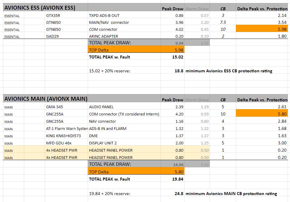
Here is my calculation to avoid a situation when the AVIONICS ESS CB trips before the equipment on this bus does. Taking care about the AVIONX ESS BUS CB in series:


The total PEAK DRAW on the AVIONX BUS is 9.04 Amps.


The biggest Delta PEAK DRAW vs CB protection is on the GTN COM connector: 5.98 Amp


When I sum up the Total BUS Peak Draw (9.04A) + Top Delta Peak of the GTN COM connection (assume this connection is shorted): TOTAL PEAK with fault on the GTN COM side equals 15.02 Amp


Adding 20% reserve - I would need 18.8 Amp minimum CB rating for the AVIONX ESS bus. Thus a 20Amp CB is enough.


The AVIONX MAIN bus would require a 25Amp CB..


Is my approach correct?
| | - The Matronics AeroElectric-List Email Forum - | | | Use the List Feature Navigator to browse the many List utilities available such as the Email Subscriptions page, Archive Search & Download, 7-Day Browse, Chat, FAQ, Photoshare, and much more:
http://www.matronics.com/Navigator?AeroElectric-List |
|
| Description: |
|
| Filesize: |
117.13 KB |
| Viewed: |
11256 Time(s) |
|
_________________
Igor
RV10 in progress |
|
| Back to top |
|
|
nuckolls.bob(at)aeroelect
Guest
|
| Posted: Sat Jul 04, 2020 9:40 am Post subject: RV10 Single Batt + Dual Alternator |
|
|
At 07:16 AM 7/4/2020, you wrote:
| Quote: | --> AeroElectric-List message posted by: "supik" <bionicad(at)hotmail.com>
Here is my calculation to avoid a situation when the AVIONICS ESS CB trips before the equipment on this bus does. Taking care about the AVIONX ESS BUS CB in series:
The total PEAK DRAW on the AVIONX BUS is 9.04 Amps.
The biggest Delta PEAK DRAW vs CB protection is on the GTN COM connector: 5.98 Amp
When I sum up the Total BUS Peak Draw (9.04A) + Top Delta Peak of the GTN COM connection (assume this connection is shorted): TOTAL PEAK with fault on the GTN COM side equals 15.02 Amp
Adding 20% reserve - I would need 18.8 Amp minimum CB rating for the AVIONX ESS bus. Thus a 20Amp CB is enough.
Is my approach correct? |
Was unable to open your .jpg . . . "file not found"
you have circuit breakers in your distribution
bus feeders?
Bob . . .
| | - The Matronics AeroElectric-List Email Forum - | | | Use the List Feature Navigator to browse the many List utilities available such as the Email Subscriptions page, Archive Search & Download, 7-Day Browse, Chat, FAQ, Photoshare, and much more:
http://www.matronics.com/Navigator?AeroElectric-List |
|
|
|
| Back to top |
|
|
supik
Joined: 22 Aug 2018
Posts: 70
|
| Posted: Sat Jul 04, 2020 4:56 pm Post subject: Re: RV10 Single Batt + Dual Alternator |
|
|
| nuckolls.bob(at)aeroelect wrote: | At 07:16 AM 7/4/2020, you wrote:
| Quote: | --> AeroElectric-List message posted by: "supik" <bionicad>
Here is my calculation to avoid a situation when the AVIONICS ESS CB trips before the equipment on this bus does. Taking care about the AVIONX ESS BUS CB in series:
The total PEAK DRAW on the AVIONX BUS is 9.04 Amps.
The biggest Delta PEAK DRAW vs CB protection is on the GTN COM connector: 5.98 Amp
When I sum up the Total BUS Peak Draw (9.04A) + Top Delta Peak of the GTN COM connection (assume this connection is shorted): TOTAL PEAK with fault on the GTN COM side equals 15.02 Amp
Adding 20% reserve - I would need 18.8 Amp minimum CB rating for the AVIONX ESS bus. Thus a 20Amp CB is enough.
Is my approach correct? |
Was unable to open your .jpg . . . "file not found"
you have circuit breakers in your distribution
bus feeders?
Bob . . . |
Affirm, all protection on the Avionics Buses are circuit breakers.
EDIT: new link to picture: https://i.ibb.co/PNw2Pfc/AVIONX-ESS-BUS-CB.jpg
| | - The Matronics AeroElectric-List Email Forum - | | | Use the List Feature Navigator to browse the many List utilities available such as the Email Subscriptions page, Archive Search & Download, 7-Day Browse, Chat, FAQ, Photoshare, and much more:
http://www.matronics.com/Navigator?AeroElectric-List |
|
_________________
Igor
RV10 in progress |
|
| Back to top |
|
|
nuckolls.bob(at)aeroelect
Guest
|
| Posted: Sun Jul 05, 2020 7:18 am Post subject: RV10 Single Batt + Dual Alternator |
|
|
| Quote: | >
> > When I sum up the Total BUS Peak Draw (9.04A) + Top Delta Peak of the GTN COM connection (assume this connection is shorted): TOTAL PEAK with fault on the GTN COM side equals 15.02 Amp
> >
> > Adding 20% reserve - I would need 18.8 Amp minimum CB rating for the AVIONX ESS bus. Thus a 20Amp CB is enough.
> >
> > Is my approach correct? |
I'm talking about the 20A cb on the bus feeder?
Bob . . .
| | - The Matronics AeroElectric-List Email Forum - | | | Use the List Feature Navigator to browse the many List utilities available such as the Email Subscriptions page, Archive Search & Download, 7-Day Browse, Chat, FAQ, Photoshare, and much more:
http://www.matronics.com/Navigator?AeroElectric-List |
|
|
|
| Back to top |
|
|
supik
Joined: 22 Aug 2018
Posts: 70
|
| Posted: Sun Jul 05, 2020 7:26 am Post subject: Re: RV10 Single Batt + Dual Alternator |
|
|
| nuckolls.bob(at)aeroelect wrote: | | Quote: | >
> > When I sum up the Total BUS Peak Draw (9.04A) + Top Delta Peak of the GTN COM connection (assume this connection is shorted): TOTAL PEAK with fault on the GTN COM side equals 15.02 Amp
> >
> > Adding 20% reserve - I would need 18.8 Amp minimum CB rating for the AVIONX ESS bus. Thus a 20Amp CB is enough.
> >
> > Is my approach correct? |
I'm talking about the 20A cb on the bus feeder?
Bob . . . |
Yes, that's a Circuit Breaker.
| | - The Matronics AeroElectric-List Email Forum - | | | Use the List Feature Navigator to browse the many List utilities available such as the Email Subscriptions page, Archive Search & Download, 7-Day Browse, Chat, FAQ, Photoshare, and much more:
http://www.matronics.com/Navigator?AeroElectric-List |
|
_________________
Igor
RV10 in progress |
|
| Back to top |
|
|
nuckolls.bob(at)aeroelect
Guest
|
| Posted: Sun Jul 05, 2020 9:21 am Post subject: RV10 Single Batt + Dual Alternator |
|
|
| Quote: |
>
> I'm talking about the 20A cb on the bus feeder?
>
>
>
> Bob . . .
Yes, it's a Circuit Breaker.
|
Could you give me that link to your current
wiring diagram again?
Bob . . .
| | - The Matronics AeroElectric-List Email Forum - | | | Use the List Feature Navigator to browse the many List utilities available such as the Email Subscriptions page, Archive Search & Download, 7-Day Browse, Chat, FAQ, Photoshare, and much more:
http://www.matronics.com/Navigator?AeroElectric-List |
|
|
|
| Back to top |
|
|
supik
Joined: 22 Aug 2018
Posts: 70
|
| Posted: Sun Jul 05, 2020 2:09 pm Post subject: Re: RV10 Single Batt + Dual Alternator |
|
|
| nuckolls.bob(at)aeroelect wrote: | | Quote: |
>
> I'm talking about the 20A cb on the bus feeder?
>
>
>
> Bob . . .
Yes, it's a Circuit Breaker.
|
Could you give me that link to your current
wiring diagram again?
Bob . . . |
Of course, here it is:
https://i.ibb.co/Z67GnDy/Diagram-OM-ELA-Igor-v-035.jpg
| | - The Matronics AeroElectric-List Email Forum - | | | Use the List Feature Navigator to browse the many List utilities available such as the Email Subscriptions page, Archive Search & Download, 7-Day Browse, Chat, FAQ, Photoshare, and much more:
http://www.matronics.com/Navigator?AeroElectric-List |
|
_________________
Igor
RV10 in progress |
|
| Back to top |
|
|
nuckolls.bob(at)aeroelect
Guest
|
| Posted: Sun Jul 05, 2020 6:03 pm Post subject: RV10 Single Batt + Dual Alternator |
|
|
Okay . . .
Avionics master switches were not birthed
out of good physics in the first place.
Their value diminished to zero about 1975
as the acceptance of DO160 qualification
really took roots.
Are there ANY avionics manufacturers
who recommend 'protecting' their products
from the ordinary vagaries of electrical
system excursions by means of special
consideration for control of their energy
sources?
The relay, switch and wiring become single
points of failure for all items on the
'protected' bus. Recommend that the breakers
on these switched buses be moved to their
respective un-switched buses thus restoring
individual circuit integrity.
Eliminate the breaker in the diode feeder
to the e-bus . . . that's your normal feed
path. Any fault that would open that breaker
puts you in greater peril than risks for
burning that path's feeders. It's an extra
gizmo with associated terminals/screws that
adds no value.
Your e-bus contactor becomes an alternate
feed path needed in case the main bus is
shut down due to loss of main alternator.
Recommend you take the aux alternator
b-lead directly to battery via fusible
link. This makes the AUX alternator
optionally available to the main bus
through one contactor.
Recommend you replace the ANL in the
main alternator b-lead with a fusible
link. Easier, lighter, simpler and just
as reliable for the intended task of
fending off an exceedingly unlikely
failure.
Recommend losing the MOV . . . diode
on the starter contactor takes care
of the coil collapse transient.
Add diodes to all other contactors/relays
as needed.
Battery current monitoring? How is this
useful in flight?
How much current does the electronic
ignition draw when aircraft is parked?
10A protection? Why not run it from
the e-bus? That's a triple-source,
double fed bus . . . it's not going
dark in your lifetime.
You're getting close . . . just a
touch of excess hardware some of which
negates the integrity of a double-fed
bus-structure.
Bob . . .
| | - The Matronics AeroElectric-List Email Forum - | | | Use the List Feature Navigator to browse the many List utilities available such as the Email Subscriptions page, Archive Search & Download, 7-Day Browse, Chat, FAQ, Photoshare, and much more:
http://www.matronics.com/Navigator?AeroElectric-List |
|
|
|
| Back to top |
|
|
supik
Joined: 22 Aug 2018
Posts: 70
|
| Posted: Wed Jul 15, 2020 12:55 pm Post subject: Re: RV10 Single Batt + Dual Alternator |
|
|
Thank you for taking the time to review my diagram and sorry for my late answer!
I hope my answers or questions do no sound ignorant. I'm trying to better understand my options (pros/cons) and that doesn't go without asking..
| Quote: | Are there ANY avionics manufacturers
who recommend 'protecting' their products
from the ordinary vagaries of electrical
system excursions by means of special
consideration for control of their energy
sources?
The relay, switch and wiring become single
points of failure for all items on the
'protected' bus. Recommend that the breakers
on these switched buses be moved to their
respective un-switched buses thus restoring
individual circuit integrity. |
I'm leaning towards eliminating the AVIONX ESS Bus and keeping the AVIONX MAIN bus for load shedding and engine start (to simply reduce load on the battery).
So my question again, how to size the AVIONX MAIN bus Circuit Breaker properly? I haven't found an 'official' guide or best practice how to acomplish this.
| Quote: | Eliminate the breaker in the diode feeder
to the e-bus . . . that's your normal feed
path. Any fault that would open that breaker
puts you in greater peril than risks for
burning that path's feeders. It's an extra
gizmo with associated terminals/screws that
adds no value.
Your e-bus contactor becomes an alternate
feed path needed in case the main bus is
shut down due to loss of main alternator. |
How is a burning feeder safer then an open CB in this case?
If the CB trips and E-BUS Contactor is open -all equipment on the MAIN BUS remains operational including the PFD, EIS and ADAHRS (these are fed from KEEP ALIVE PWR through the GAD27 unit).
The main issue would be: PITCH TRIM lost.
The E-BUS Contactor is normally always On with the ALT-2 ON (on standby).-single 3way switch
Talking about single point of failure (with the ESS BUS CB eliminated): How would you manage a hard fault on the ESSENTIAL BUS with no option to isolate it other than opening both the MAIN BUS and E-BUS contactors?
You are left with the own battery powered standby EFIS - how would you bring the aircraft down in IMC at night? no nav, no com; maybe with the ipad and geo referenced charts 
| Quote: | Recommend you take the aux alternator
b-lead directly to battery via fusible
link. This makes the AUX alternator
optionally available to the main bus
through one contactor.
Recommend you replace the ANL in the
main alternator b-lead with a fusible
link. Easier, lighter, simpler and just
as reliable for the intended task of
fending off an exceedingly unlikely
failure. |
This will require a separate, long (rv10), always hot conductor from the alternator to the tail of the airplane. With the current setup I could avoid the extra wire. What exactly speaks against running the B lead to the E-BUS?
| Quote: | Recommend losing the MOV . . . diode
on the starter contactor takes care
of the coil collapse transient. |
willco
| Quote: | Add diodes to all other contactors/relays
as needed. |
willco
| Quote: | Battery current monitoring? How is this
useful in flight? |
not much, I will eliminate it.
Would it make more sense in a setup with single Alternator for load shedding in case of ALT failure..?
| Quote: | How much current does the electronic
ignition draw when aircraft is parked?
10A protection? Why not run it from
the e-bus? That's a triple-source,
double fed bus . . . it's not going
dark in your lifetime. |
This is wired per manufacturers diagram: It's always hot. In case of elec smoke/fire the pilot would open the MAIN BAT contactor (in my case the ESS BUS contactor too) and the ignition stays unaffected. The 10A protection is supplied and required by SUREFLY.
The current draw in standby mode (unit off) is .001mA
| | - The Matronics AeroElectric-List Email Forum - | | | Use the List Feature Navigator to browse the many List utilities available such as the Email Subscriptions page, Archive Search & Download, 7-Day Browse, Chat, FAQ, Photoshare, and much more:
http://www.matronics.com/Navigator?AeroElectric-List |
|
_________________
Igor
RV10 in progress |
|
| Back to top |
|
|
supik
Joined: 22 Aug 2018
Posts: 70
|
| Posted: Wed Jul 15, 2020 2:16 pm Post subject: Re: RV10 Single Batt + Dual Alternator |
|
|
One more question regarding the AVIONX relay/switch combo.


Some builders suggested to use a NC relay, so that in case the relay or switch fails - power to the avionics bus would still be available. I can only think of the CB protecting the wire to the relay as  SPOF..


-thoughts on this kind of setup?
| | - The Matronics AeroElectric-List Email Forum - | | | Use the List Feature Navigator to browse the many List utilities available such as the Email Subscriptions page, Archive Search & Download, 7-Day Browse, Chat, FAQ, Photoshare, and much more:
http://www.matronics.com/Navigator?AeroElectric-List |
|
_________________
Igor
RV10 in progress |
|
| Back to top |
|
|
|
|
You cannot post new topics in this forum
You cannot reply to topics in this forum
You cannot edit your posts in this forum
You cannot delete your posts in this forum
You cannot vote in polls in this forum
You cannot attach files in this forum
You can download files in this forum
|
Powered by phpBB © 2001, 2005 phpBB Group
|

