 |
Matronics Email Lists
Web Forum Interface to the Matronics Email Lists
|
| View previous topic :: View next topic |
| Author |
Message |
peter.feneht(at)gmail.com
Guest
|
 Posted: Wed Nov 13, 2019 1:56 pm Post subject: draft schematic attached Posted: Wed Nov 13, 2019 1:56 pm Post subject: draft schematic attached |
 |
|
Hello to Bob and the Group,

Can someone advise me on the attached schematic?  It is a pdf file.

Thanks!

--Peter
| | - The Matronics AeroElectric-List Email Forum - | | | Use the List Feature Navigator to browse the many List utilities available such as the Email Subscriptions page, Archive Search & Download, 7-Day Browse, Chat, FAQ, Photoshare, and much more:
http://www.matronics.com/Navigator?AeroElectric-List |
|
| Description: |
|

Download |
| Filename: |
Peters_draft_Xenos_schematic.pdf |
| Filesize: |
347.88 KB |
| Downloaded: |
379 Time(s) |
|
|
| Back to top |
|
 |
user9253
Joined: 28 Mar 2008
Posts: 1908
Location: Riley TWP Michigan
|
| Posted: Wed Nov 13, 2019 4:30 pm Post subject: Re: draft schematic attached |
|
|
The 20 amp alternator fuse is way too small.  The purpose of that fuse is to protect the battery from short circuits.

The fuse should be physically located near the contactors.

Use 18AWG for voltage regulator wires.  The 5 amp regulator fuse is OK.

The panel switch and 5 amp fuse are not needed or desired.  Eliminate them.  They are unnecessary failure points.  Consider using 10AWG for the power bus feeder.

The 12AWG wire going to the starter contactor is too big.  Replace it with 18AWG.  That wire needs to be fused.  5 amp should be good.

The 14AWG wires connected to the power bus are too big.  Replace them with 18AWG.

Protect those wires with 5 amp fuses.  Manufacturer's instructions take precedence over my recommendations.
| | - The Matronics AeroElectric-List Email Forum - | | | Use the List Feature Navigator to browse the many List utilities available such as the Email Subscriptions page, Archive Search & Download, 7-Day Browse, Chat, FAQ, Photoshare, and much more:
http://www.matronics.com/Navigator?AeroElectric-List |
|
_________________
Joe Gores |
|
| Back to top |
|
|
cluros(at)gmail.com
Guest
|
| Posted: Wed Nov 13, 2019 7:43 pm Post subject: draft schematic attached |
|
|
I'd remove the panel switch.
On Wed, Nov 13, 2019 at 2:03 PM Peter Feneht <peter.feneht(at)gmail.com (peter.feneht(at)gmail.com)> wrote:
| Quote: | Hello to Bob and the Group,
Can someone advise me on the attached schematic? It is a pdf file.
Thanks!
--Peter
|
| | - The Matronics AeroElectric-List Email Forum - | | | Use the List Feature Navigator to browse the many List utilities available such as the Email Subscriptions page, Archive Search & Download, 7-Day Browse, Chat, FAQ, Photoshare, and much more:
http://www.matronics.com/Navigator?AeroElectric-List |
|
|
|
| Back to top |
|
|
peter.feneht(at)gmail.com
Guest
|
| Posted: Thu Nov 14, 2019 4:48 pm Post subject: draft schematic attached |
|
|
Thanks! -pf
On Wed, Nov 13, 2019 at 6:35 PM user9253 <fransew(at)gmail.com (fransew(at)gmail.com)> wrote:
| Quote: | --> AeroElectric-List message posted by: "user9253" <fransew(at)gmail.com (fransew(at)gmail.com)>
The 20 amp alternator fuse is way too small. The purpose of that fuse is to protect the battery from short circuits.
The fuse should be physically located near the contactors.
Use 18AWG for voltage regulator wires. The 5 amp regulator fuse is OK.
The panel switch and 5 amp fuse are not needed or desired. Eliminate them. They are unnecessary failure points. Consider using 10AWG for the power bus feeder.
The 12AWG wire going to the starter contactor is too big. Replace it with 18AWG. That wire needs to be fused. 5 amp should be good.
The 14AWG wires connected to the power bus are too big. Replace them with 18AWG.
Protect those wires with 5 amp fuses. Manufacturer's instructions take precedence over my recommendations.
--------
Joe Gores
Read this topic online here:
http://forums.matronics.com/viewtopic.php?p=492871#492871
===========
br> fts!)
r> > rel="noreferrer" target="_blank">http://www.matronics.com/contribution
     -Matt Dralle, List Admin.
===========
-
Electric-List" rel="noreferrer" target="_blank">http://www.matronics.com/Navigator?AeroElectric-List
===========
FORUMS -
eferrer" target="_blank">http://forums.matronics.com
===========
WIKI -
errer" target="_blank">http://wiki.matronics.com
===========
b Site -
     -Matt Dralle, List Admin.
rel="noreferrer" target="_blank">http://www.matronics.com/contribution
===========
|
| | - The Matronics AeroElectric-List Email Forum - | | | Use the List Feature Navigator to browse the many List utilities available such as the Email Subscriptions page, Archive Search & Download, 7-Day Browse, Chat, FAQ, Photoshare, and much more:
http://www.matronics.com/Navigator?AeroElectric-List |
|
|
|
| Back to top |
|
|
bob.verwey(at)gmail.com
Guest
|
| Posted: Fri Nov 15, 2019 12:05 am Post subject: draft schematic attached |
|
|
Hi Peter
Please let us have a copy of that updated drawing after the edits as suggested by Joe?Â
Best...Bob Verwey
082 331 2727
[img]https://docs.google.com/uc?export=download&id=0B5d7rgAInTuTUUZsUjY4QmJsdVU&revid=0B5d7rgAInTuTdDJDaXRFZVh3b3lMa3FWL0s3MFdzc01YRlNvPQ[/img]
On Fri, 15 Nov 2019 at 02:53, Peter Feneht <peter.feneht(at)gmail.com (peter.feneht(at)gmail.com)> wrote:
| Quote: | Thanks! -pf
On Wed, Nov 13, 2019 at 6:35 PM user9253 <fransew(at)gmail.com (fransew(at)gmail.com)> wrote:
| Quote: | --> AeroElectric-List message posted by: "user9253" <fransew(at)gmail.com (fransew(at)gmail.com)>
The 20 amp alternator fuse is way too small. The purpose of that fuse is to protect the battery from short circuits.
The fuse should be physically located near the contactors.
Use 18AWG for voltage regulator wires. The 5 amp regulator fuse is OK.
The panel switch and 5 amp fuse are not needed or desired. Eliminate them. They are unnecessary failure points. Consider using 10AWG for the power bus feeder.
The 12AWG wire going to the starter contactor is too big. Replace it with 18AWG. That wire needs to be fused. 5 amp should be good.
The 14AWG wires connected to the power bus are too big. Replace them with 18AWG.
Protect those wires with 5 amp fuses. Manufacturer's instructions take precedence over my recommendations.
--------
Joe Gores
Read this topic online here:
http://forums.matronics.com/viewtopic.php?p=492871#492871
===========
br> fts!)
r> > rel="noreferrer" target="_blank">http://www.matronics.com/contribution
     -Matt Dralle, List Admin.
===========
-
Electric-List" rel="noreferrer" target="_blank">http://www.matronics.com/Navigator?AeroElectric-List
===========
FORUMS -
eferrer" target="_blank">http://forums.matronics.com
===========
WIKI -
errer" target="_blank">http://wiki.matronics.com
===========
b Site -
     -Matt Dralle, List Admin.
rel="noreferrer" target="_blank">http://www.matronics.com/contribution
===========
|
|
| | - The Matronics AeroElectric-List Email Forum - | | | Use the List Feature Navigator to browse the many List utilities available such as the Email Subscriptions page, Archive Search & Download, 7-Day Browse, Chat, FAQ, Photoshare, and much more:
http://www.matronics.com/Navigator?AeroElectric-List |
|
|
|
| Back to top |
|
|
peter.feneht(at)gmail.com
Guest
|
| Posted: Sun Nov 17, 2019 3:35 pm Post subject: draft schematic attached |
|
|
Bob Verwey generously encouraged me to send my revised schematic abased on Joe Gores' advice. In addition, I attached a conceptual layout of the panel. I am mystified by how to go from these drawings to the actual physical systems. I am seriously considering the Vertical Power system. I am hoping their motto is correct, 'easier, safer, better' - and even if theoretically I could do it less expensively without it, I might be willing to put extra money toward the VP system for those qualities. Thanks in advance for any additional advice you have to offer.
best. Peter
On Fri, Nov 15, 2019 at 2:09 AM Bob Verwey <bob.verwey(at)gmail.com (bob.verwey(at)gmail.com)> wrote:
| Quote: | Hi Peter
Please let us have a copy of that updated drawing after the edits as suggested by Joe?Â
Best...Bob Verwey
082 331 2727
[img]https://docs.google.com/uc?export=download&id=0B5d7rgAInTuTUUZsUjY4QmJsdVU&revid=0B5d7rgAInTuTdDJDaXRFZVh3b3lMa3FWL0s3MFdzc01YRlNvPQ[/img]
On Fri, 15 Nov 2019 at 02:53, Peter Feneht <peter.feneht(at)gmail.com (peter.feneht(at)gmail.com)> wrote:
| Quote: | Thanks! -pf
On Wed, Nov 13, 2019 at 6:35 PM user9253 <fransew(at)gmail.com (fransew(at)gmail.com)> wrote:
| Quote: | --> AeroElectric-List message posted by: "user9253" <fransew(at)gmail.com (fransew(at)gmail.com)>
The 20 amp alternator fuse is way too small. The purpose of that fuse is to protect the battery from short circuits.
The fuse should be physically located near the contactors.
Use 18AWG for voltage regulator wires. The 5 amp regulator fuse is OK.
The panel switch and 5 amp fuse are not needed or desired. Eliminate them. They are unnecessary failure points. Consider using 10AWG for the power bus feeder.
The 12AWG wire going to the starter contactor is too big. Replace it with 18AWG. That wire needs to be fused. 5 amp should be good.
The 14AWG wires connected to the power bus are too big. Replace them with 18AWG.
Protect those wires with 5 amp fuses. Manufacturer's instructions take precedence over my recommendations.
--------
Joe Gores
Read this topic online here:
http://forums.matronics.com/viewtopic.php?p=492871#492871
===========
br> fts!)
r> > rel="noreferrer" target="_blank">http://www.matronics.com/contribution
     -Matt Dralle, List Admin.
===========
-
Electric-List" rel="noreferrer" target="_blank">http://www.matronics.com/Navigator?AeroElectric-List
===========
FORUMS -
eferrer" target="_blank">http://forums.matronics.com
===========
WIKI -
errer" target="_blank">http://wiki.matronics.com
===========
b Site -
     -Matt Dralle, List Admin.
rel="noreferrer" target="_blank">http://www.matronics.com/contribution
===========
|
|
|
| | - The Matronics AeroElectric-List Email Forum - | | | Use the List Feature Navigator to browse the many List utilities available such as the Email Subscriptions page, Archive Search & Download, 7-Day Browse, Chat, FAQ, Photoshare, and much more:
http://www.matronics.com/Navigator?AeroElectric-List |
|
| Description: |
|
Download |
| Filename: |
Xenos_panel_layout,_11-17-19.pdf |
| Filesize: |
235.05 KB |
| Downloaded: |
314 Time(s) |
| Description: |
|
Download |
| Filename: |
Xenos_e-schem,_11-17-19.pdf |
| Filesize: |
316.73 KB |
| Downloaded: |
434 Time(s) |
|
|
| Back to top |
|
|
user9253
Joined: 28 Mar 2008
Posts: 1908
Location: Riley TWP Michigan
|
| Posted: Sun Nov 17, 2019 4:45 pm Post subject: Re: draft schematic attached |
|
|
No doubt that Vertical Power performs as advertised.  There are lots of satisfied customers.

Vertical Power will provide lots of data that could come in handy for troubleshooting.  But there are some disadvantages:

It costs more than fuses.

If it breaks, can you fix it yourself?

If it becomes necessary to repair, will your plane be out of service?

Will the company ever go out of business?

If wiring a basic electrical system with fuses proves to be challenging, then so will wiring Vertical Power.

Here is an interesting thread about fuses:

http://forums.matronics.com/viewtopic.php?t=16762261&sid=ee7724058fb26b668cd6e7bd436dcf2b
| | - The Matronics AeroElectric-List Email Forum - | | | Use the List Feature Navigator to browse the many List utilities available such as the Email Subscriptions page, Archive Search & Download, 7-Day Browse, Chat, FAQ, Photoshare, and much more:
http://www.matronics.com/Navigator?AeroElectric-List |
|
_________________
Joe Gores |
|
| Back to top |
|
|
nuckolls.bob(at)aeroelect
Guest
|
| Posted: Sun Nov 17, 2019 5:42 pm Post subject: draft schematic attached |
|
|
At 05:33 PM 11/17/2019, you wrote:
| Quote: | | Bob Verwey generously encouraged me to send my revised schematic abased on Joe Gores' advice. In addition, I attached a conceptual layout of the panel. I am mystified by how to go from these drawings to the actual physical systems. I am seriously considering the Vertical Power system. |
The VP option means that you toss out all you've
done so far and start over . . .
| Quote: | | Â I am hoping their motto is correct, 'easier, safer, better' |
. . . not quantitative.
| Quote: | - and even if theoretically I could do it less expensively without it
I might be willing to put extra money toward the VP system for those
qualities. Thanks in advance for any additional advice you have to offer. |
I've worked dozens of aircraft accident investigations.
I've read many more final reports on bad-days-in-the-cockpit.
Only a tiny percentage of accidents are precipitated or
advanced due to electrical system failures. Accidents
that started with electrical failures were found to have
root cause in poor judgement in electrical system management,
design and/or fabrication.
I would call your attention to accidents discussed in
http://www.aeroelectric.com/Reference_Docs/Accidents/N811HB_Feb2008_LA-IVp/
and
http://www.aeroelectric.com/Reference_Docs/Accidents/N289DT_Nov2010_RV-10/Dan_Lloyd_RV-10_Accident.pdf
. . . two examples of serious accidents precipitated
by poor craftsmanship and/or design decisions.
We've had numerous discussions over the years
exploring the manner in which ignorance of
electrical system functionality produced situations
that didn't need to happen. Here's one we studied
here on the List 15 years ago:
https://tinyurl.com/kqo7jx8
Building a failure tolerant electrical system is
really easy. It begins with two processes
you have already implemented: (1) propose an
architecture and (2) seek peer review. These
are best followed with continuous conversation
with knowledgeable/experienced individuals
as your project moves along.
The goal is to have an UNDERSTANDING of how
all the bits-and-pieces fit into the system . . .
a quality that you don't get in flight school.
Finally, it behooves you to have a plan-B
for worst case failure . . . the totally
dark panel. I've never owned an a cross-country
capable airplane . . . but I've rented dozens
of different machines. Not once did I concern
myself with the airplane's electrical system
service history . . . I carried this stuff
in the flight bag.
https://tinyurl.com/qw73hkd
I was always prepared to get where I had
intended to go whether or not the stuff on
the panel was working. In fact, most of
my cross-country navigation was conducted
with DUAL, $100 GPS hand-helds purchase
at Walmart . . . I've never bothered to
turn on the super-whippy GPS system
in a rental airplane. They were all
different and came with a 1-inch thick
owner's manual. I didn't what to take the
time to learn a new system with each rental
when my personal hand-helds got me there
and back again with accuracy and confidence.
You cannot purchase understanding or confidence
in your electrical system. Poor craftsmanship
can render all the gee-whiz features of a VP
system useless. I'm not suggesting that
the VP products do not function well as
advertised. But I would rather you craft
a system with a confidence that arises
from understanding and save a lot of money . . .
dollars that would no doubt put some handy
plan-b hardware in your flight bag.
You're off to an excellent start . . .
Bob . . .
| | - The Matronics AeroElectric-List Email Forum - | | | Use the List Feature Navigator to browse the many List utilities available such as the Email Subscriptions page, Archive Search & Download, 7-Day Browse, Chat, FAQ, Photoshare, and much more:
http://www.matronics.com/Navigator?AeroElectric-List |
|
|
|
| Back to top |
|
|
ceengland7(at)gmail.com
Guest
|
| Posted: Mon Nov 18, 2019 7:34 am Post subject: draft schematic attached |
|
|
Hi Peter,
I don't know about everyone else, but it's a lot simpler for me to open .jpg files than .pdf. In my email client, I can open jpg directly, but I must first download, then run a pdf viewer.
Charlie
On 11/17/2019 5:33 PM, Peter Feneht wrote:
| Quote: | Bob Verwey generously encouraged me to send my revised schematic abased on Joe Gores' advice. In addition, I attached a conceptual layout of the panel. I am mystified by how to go from these drawings to the actual physical systems. I am seriously considering the Vertical Power system. I am hoping their motto is correct, 'easier, safer, better' - and even if theoretically I could do it less expensively without it, I might be willing to put extra money toward the VP system for those qualities. Thanks in advance for any additional advice you have to offer.
best. Peter
On Fri, Nov 15, 2019 at 2:09 AM Bob Verwey <bob.verwey(at)gmail.com (bob.verwey(at)gmail.com)> wrote:
| Quote: | Hi Peter
Please let us have a copy of that updated drawing after the edits as suggested by Joe?Â
Best... Bob Verwey
082 331 2727
[img]https://docs.google.com/uc?export=download&id=0B5d7rgAInTuTUUZsUjY4QmJsdVU&revid=0B5d7rgAInTuTdDJDaXRFZVh3b3lMa3FWL0s3MFdzc01YRlNvPQ[/img]
On Fri, 15 Nov 2019 at 02:53, Peter Feneht <peter.feneht(at)gmail.com (peter.feneht(at)gmail.com)> wrote:
| Quote: | Thanks! -pf
On Wed, Nov 13, 2019 at 6:35 PM user9253 <fransew(at)gmail.com (fransew(at)gmail.com)> wrote:
| Quote: | --> AeroElectric-List message posted by: "user9253" <fransew(at)gmail.com (fransew(at)gmail.com)>
The 20 amp alternator fuse is way too small. The purpose of that fuse is to protect the battery from short circuits.
The fuse should be physically located near the contactors.
Use 18AWG for voltage regulator wires. The 5 amp regulator fuse is OK.
The panel switch and 5 amp fuse are not needed or desired. Eliminate them. They are unnecessary failure points. Consider using 10AWG for the power bus feeder.
The 12AWG wire going to the starter contactor is too big. Replace it with 18AWG. That wire needs to be fused. 5 amp should be good.
The 14AWG wires connected to the power bus are too big. Replace them with 18AWG.
Protect those wires with 5 amp fuses. Manufacturer's instructions take precedence over my recommendations.
--------
Joe Gores
|
|
|
|
| | - The Matronics AeroElectric-List Email Forum - | | | Use the List Feature Navigator to browse the many List utilities available such as the Email Subscriptions page, Archive Search & Download, 7-Day Browse, Chat, FAQ, Photoshare, and much more:
http://www.matronics.com/Navigator?AeroElectric-List |
|
|
|
| Back to top |
|
|
peter.feneht(at)gmail.com
Guest
|
| Posted: Mon Nov 18, 2019 9:23 am Post subject: draft schematic attached |
|
|
Bob - I really recognize and agree with the wisdom in the generous advice
that you gave me, super thanks!! You are right, if I build the system that
reflects my understanding of the system, then I can see all the separate
items for maintenance, repair, etc. The VP would be a large 'black box'
that I would have to learn to accept. I like your 'grass roots' type of
approach.
thanks. --Peter
On Sun, Nov 17, 2019 at 7:50 PM Robert L. Nuckolls, III <
nuckolls.bob(at)aeroelectric.com> wrote:
[quote] At 05:33 PM 11/17/2019, you wrote:
Bob Verwey generously encouraged me to send my revised schematic abased on
Joe Gores' advice.Ã In addition, I attached a conceptual layout of the
panel.Ã I am mystified by how to go from these drawings to the actual
physical systems.Ã I am seriously considering the Vertical Power system.
The VP option means that you toss out all you've
done so far and start over . . .
à I am hoping their motto is correct, 'easier, safer, better'
. . . not quantitative.
- and even if theoretically I could do it less expensively without it
I might be willing to put extra money toward the VP system for those
qualities. Thanks in advance for any additional advice you have to offer
| | - The Matronics AeroElectric-List Email Forum - | | | Use the List Feature Navigator to browse the many List utilities available such as the Email Subscriptions page, Archive Search & Download, 7-Day Browse, Chat, FAQ, Photoshare, and much more:
http://www.matronics.com/Navigator?AeroElectric-List |
|
|
|
| Back to top |
|
|
Eric Page
Joined: 15 Feb 2017
Posts: 242
|
| Posted: Mon Nov 18, 2019 10:02 am Post subject: draft schematic attached |
|
|
Charlie,

PDF has become the de facto standard for online document transfer.  Everyone uses it because *any* software package can "print" to a PDF engine to create it, and it solves the problems of incompatible document formats or recipients not having the right software package.  PDF is probably one of the top ten most useful -- and most used -- inventions since the dawn of the internet.

As an aside, I sold a house a few years ago while whizzing through the western Arizona desert at 70 mph, by electronically signing multiple PDF documents on my iPad (my father was driving).  I met my listing agent only once, when she came to look at the house.  Everything else was done with PDFs.

I notice you use a gmail account.  If you really don't want to deal with downloading to your local machine, the gmail web interface will display PDFs in your browser.

Cheers,

Eric

do not archive


                                                                    On Monday, November 18, 2019, 06:44:21 AM HST, Charlie England <ceengland7(at)gmail.com> wrote:

                 I don't know about everyone else, but it's a lot simpler for me to       open .jpg files than .pdf. In my email client, I can open jpg       directly, but I must first download, then run a pdf viewer.


       Charlie
| | - The Matronics AeroElectric-List Email Forum - | | | Use the List Feature Navigator to browse the many List utilities available such as the Email Subscriptions page, Archive Search & Download, 7-Day Browse, Chat, FAQ, Photoshare, and much more:
http://www.matronics.com/Navigator?AeroElectric-List |
|
|
|
| Back to top |
|
|
nuckolls.bob(at)aeroelect
Guest
|
| Posted: Mon Nov 18, 2019 10:51 am Post subject: draft schematic attached |
|
|
At 11:20 AM 11/18/2019, you wrote:
| Quote: | | Bob - I really recognize and agree with the wisdom in the generous advice that you gave me, super thanks!! You are right, if I build the system that reflects my understanding of the system, then I can see all the separate items for maintenance, repair, etc. The VP would be a large 'black box' that I would have to learn to accept. I like your 'grass roots' type of approach. |
You are most welcome. From the get-go of this
List, primary goals are topped off with
offering time, talent and resources that
go to understanding how to fabricate and
operate a failure-tolerant system.
Worked many years in the T/C world where
pilots were at risk for becoming passengers
in their own machines. See:
http://www.aeroelectric.com/Reference_Docs/Accidents/N26DK_Mar2013/20130317-0_PRM1_N26DK.pdf
This airplane bit the dust after 'total electrical
failure', amongst other things. Yet, the ship's
battery was not returned to Concord until about
a year after the accident. After all this time,
the battery still contained a substantial percentage
of full capacity . . . the exact number escapes
me but it was on the order of 80%. The battery
was cycled in the lab and came up to normal
capacity.
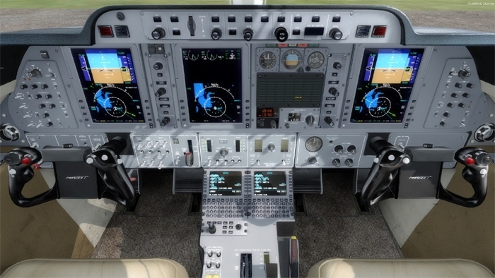
A review of the report describes several lapses in
pilot training/understanding. Yet this was a nearly
new biz-jet with a whole panel full of
high-dollar whiz-bangs. But with his battery switch
in STANDBY . . . the really useful things were
not working.
[img]cid:.0[/img]
Nearly ALL dark-n-stormy night stories in
the popular journals demonstrate similar
lapses in understanding. Fortunately, the
journal stories had happy endings . . .
the pilot survived to offer his own i-learned-about-
flying-from-that narrative.
I can assure you that the most 'reliable'
systems are simple, light, low-cost and
easily understood by a pilot who does
not choose to become an electrical engineer.
Such systems minimize AUTOMATIC operations
to critical functions that are not (1)
immediately failure-annunciated and (2)
backed up with a MANUALLY implemented plan-B.
Bob . . .
| | - The Matronics AeroElectric-List Email Forum - | | | Use the List Feature Navigator to browse the many List utilities available such as the Email Subscriptions page, Archive Search & Download, 7-Day Browse, Chat, FAQ, Photoshare, and much more:
http://www.matronics.com/Navigator?AeroElectric-List |
|
| Description: |
|
| Filesize: |
230.95 KB |
| Viewed: |
6634 Time(s) |

|
|
|
| Back to top |
|
|
jluckey(at)pacbell.net
Guest
|
| Posted: Mon Nov 18, 2019 11:02 am Post subject: draft schematic attached |
|
|
Peter,
I will add my 2 cents to this thread...
Re VP: I have to say that spending kilo-dollars to do something as elementary as power distribution seems like overkill. For less that a few hundred dollars, you can create a distribution panel using circuit breakers that accomplish the same mission as VP. (and even less $ if you elect to use fuses)
Circuit breakers (my personal choice) are inexpensive, have a proven track record (been in use for decades), are individual/independent - i.e. if one fails it does not affect the others. They have a very simple "user interface". You can tell whether it's tripped by looking at it. They don't require any software to use, program, or configure. They just work.
If you're operating B777 which has 100s of branch circuits, then electronic power distribution is certainly warranted. But for our little experimentals, it's most definitely overkill.
I often wonder what a pilot would do when he's trying to get home on a Sunday afternoon and something goes wrong w/ the VP system. There are no user-serviceable parts in one of those devices. Is the problem isolated to just one circuit? Is the whole system compromised? Is my panel gonna go dark 15 minutes after take off? I don't know. It would make me kinda nervous. Disclaimer: I don't own any VP products and I don't know enough about them to answer those questions. But I would certainly want satisfactory answers before considering that product. (still pricey, though)
The following is something I wrote that summarizes many of the design concepts that BobN & people on this list promote (all good ideas). I'm building an RV-7 and I enjoy helping friends & fellow builders with their electrical systems.
For those who are not electronically inclined, dealing with the electrical system in an
experimental airplane can seem a little overwhelming. If you're not sure how to get
started, need help sifting through all the options, or just need a little coaching, this site
is here to help.
Electrical systems in experimental aircraft donât need to be really complicated. The
basic principles are pretty straightforward and the skills required to do satisfactory
electrical work are definitely learnable by just about anyone who is capable of putting
an airframe together.
Letâs face it; electricity can be a little scary. When things go wrong, electrical
components can create sparks, get really hot, and just plain not work for no apparent
reason. Letting the magic smoke out of that new gizmo can be expensive
and embarrassing.
I think that the electrical system in an experimental airplane should have the following
characteristics. It should be:
1. Tolerate failure of any single component & end flight without an emergency
2. Reliable
3. Easy to operate
4. Easy to repair/maintain
5. Use standard components that are readily available
6. Cost effective
Those goals can be accomplished with a little effort and some help from the good folks on this List.
Jeff Luckey
KCMA
On Monday, November 18, 2019, 09:31:49 AM PST, Peter Feneht <peter.feneht(at)gmail.com> wrote:
Bob - I really recognize and agree with the wisdom in the generous advice that you gave me, super thanks!! You are right, if I build the system that reflects my understanding of the system, then I can see all the separate items for maintenance, repair, etc. The VP would be a large 'black box' that I would have to learn to accept. I like your 'grass roots' type of approach.
thanks. --Peter
On Sun, Nov 17, 2019 at 7:50 PM Robert L. Nuckolls, III <nuckolls.bob(at)aeroelectric.com (nuckolls.bob(at)aeroelectric.com)> wrote:
| Quote: | At 05:33 PM 11/17/2019, you wrote: | Quote: | | Bob Verwey generously encouraged me to send my revised schematic abased on Joe Gores' advice.Ã In addition, I attached a conceptual layout of the panel.Ã I am mystified by how to go from these drawings to the actual physical systems.Ã I am seriously considering the Vertical Power system. |
The VP option means that you toss out all you've done so far and start over . . . | Quote: | | Ã I am hoping their motto is correct, 'easier, safer, better' |
. . . not quantitative. | Quote: | | - and even if theoretically I could do it less expensively without it I might be willing to put extra money toward the VP system for those qualities. Thanks in advance for any additional advice you have to offer. |
I've worked dozens of aircraft accident investigations. I've read many more final reports on bad-days-in-the-cockpit. Only a tiny percentage of accidents are precipitated or advanced due to electrical system failures. Accidents that started with electrical failures were found to have root cause in poor judgement in electrical system management, design and/or fabrication. I would call your attention to accidents discussed in http://www.aeroelectric.com/Reference_Docs/Accidents/N811HB_Feb2008_LA-IVp/ and http://www.aeroelectric.com/Reference_Docs/Accidents/N289DT_Nov2010_RV-10/Dan_Lloyd_RV-10_Accident.pdf . . . two examples of serious accidents precipitated by poor craftsmanship and/or design decisions. We've had numerous discussions over the years exploring the manner in which ignorance of electrical system functionality produced situations that didn't need to happen. Here's one we studied here on the List 15 years ago: https://tinyurl.com/kqo7jx8 Building a failure tolerant electrical system is really easy. It begins with two processes you have already implemented: (1) propose an architecture and (2) seek peer review. These are best followed with continuous conversation with knowledgeable/experienced individuals as your project moves along. The goal is to have an UNDERSTANDING of how all the bits-and-pieces fit into the system . . . a quality that you don't get in flight school. Finally, it behooves you to have a plan-B for worst case failure . . . the totally dark panel. I've never owned an a cross-country capable airplane . . . but I've rented dozens of different machines. Not once did I concern myself with the airplane's electrical system service history . . . I carried this stuff in the flight bag. https://tinyurl.com/qw73hkd I was always prepared to get where I had intended to go whether or not the stuff on the panel was working. In fact, most of my cross-country navigation was conducted with DUAL, $100 GPS hand-helds purchase at Walmart . . . I've never bothered to turn on the super-whippy GPS system in a rental airplane. They were all different and came with a 1-inch thick owner's manual. I didn't what to take the time to learn a new system with each rental when my personal hand-helds got me there and back again with accuracy and confidence. You cannot purchase understanding or confidence in your electrical system. Poor craftsmanship can render all the gee-whiz features of a VP system useless. I'm not suggesting that the VP products do not function well as advertised. But I would rather you craft a system with a confidence that arises from understanding and save a lot of money . . . dollars that would no doubt put some handy plan-b hardware in your flight bag. You're off to an excellent start . . .
Bob . . .
|
| | - The Matronics AeroElectric-List Email Forum - | | | Use the List Feature Navigator to browse the many List utilities available such as the Email Subscriptions page, Archive Search & Download, 7-Day Browse, Chat, FAQ, Photoshare, and much more:
http://www.matronics.com/Navigator?AeroElectric-List |
|
|
|
| Back to top |
|
|
nuckolls.bob(at)aeroelect
Guest
|
| Posted: Mon Nov 18, 2019 7:04 pm Post subject: draft schematic attached |
|
|
At 11:20 AM 11/18/2019, you wrote:
| Quote: | | Bob - I really recognize and agree with the wisdom in the generous advice that you gave me, super thanks!! You are right, if I build the system that reflects my understanding of the system, then I can see all the separate items for maintenance, repair, etc. The VP would be a large 'black box' that I would have to learn to accept. I like your 'grass roots' type of approach. |
You are most welcome. From the get-go of this
List, primary goals are topped off with
offering time, talent and resources that
go to understanding how to fabricate and
operate a failure-tolerant system.
Worked many years in the T/C world where
pilots were at risk for becoming passengers
in their own machines. See:
http://www.aeroelectric.com/Reference_Docs/Accidents/N26DK_Mar2013/20130317-0_PRM1_N26DK.pdf
This airplane bit the dust after 'total electrical
failure', amongst other things. Yet, the ship's
battery was not returned to Concord until about
a year after the accident. After all this time,
the battery still contained a substantial percentage
of full capacity . . . the exact number escapes
me but it was on the order of 80%. The battery
was cycled in the lab and came up to normal
capacity.
A review of the report describes several lapses in
pilot training/understanding. Yet this was a nearly
new biz-jet with a whole panel full of
high-dollar whiz-bangs. However, with his battery switch
in STANDBY . . . some really useful things were
not working.
[img]cid:.0[/img]
Nearly ALL dark-n-stormy night stories in
the popular journals demonstrate similar
lapses in understanding. Fortunately, the
journal stories had happy endings . . .
the pilot survived to offer his own i-learned-about-
flying-from-that narrative (See Chapter 17
in the 'Connection).
I can assure you that the most 'reliable'
systems are simple, light, low-cost yet
easily understood by a pilot who
chooses not to become an electrical engineer.
Such systems minimize AUTOMATIC operations
to critical functions that are not (1)
immediately failure-annunciated and (2)
backed up with a MANUALLY implemented plan-B.
My all time favorite reliability study
ASSUMES that things WILL fail. There
is a process call Failure Mode Effects
Analysis whereby one deduces the effects
for failure of ANY single component in
the system.
1. How many ways can this part fail?
2. How will each failure affect system operation?
3. How will I know it failed?
4. Is the failure pre-flight detectable?
5. Is failure of this part, in any failure mode, likely to create
a hazard to flight?
6. Will failure of this part be likely to overtax my piloting
skills for comfortably terminating the flight?
Having conducted hundreds of FMEA studies I have concluded:
Nuckolls' first law of airplane systems design sez: "Things
break"
The second: "Systems shall be designed so that when a thing
breaks, no immediate hazard is created."
The third: "Things needed for comfortable termination of
flight requires backup or special consideration to insure
operational availability"
The forth: "Upgrading the quality, reliability, longevity, or
capability of a part shall be because you're tired of replacing
it or want some new feature, not because it damned near got
you killed."
All this may sound ominous and profound but it's
really simple. As you evolve your proposed architecture,
advise us how you plan to use the airplane. Are there
potential mission conditions that elevate risk for
any given failure? I'll bet that the aggregate
aviation experience here on the List would be
measured in centuries. Let's talk about your
design and mission goals . . . by the time
all the sands are sifted, you'll end up with
a very flight-worthy project with reliability
borne of your own understanding.
Bob . . .
| | - The Matronics AeroElectric-List Email Forum - | | | Use the List Feature Navigator to browse the many List utilities available such as the Email Subscriptions page, Archive Search & Download, 7-Day Browse, Chat, FAQ, Photoshare, and much more:
http://www.matronics.com/Navigator?AeroElectric-List |
|
| Description: |
|
| Filesize: |
229.35 KB |
| Viewed: |
6625 Time(s) |
|
|
|
| Back to top |
|
|
|
|
You cannot post new topics in this forum
You cannot reply to topics in this forum
You cannot edit your posts in this forum
You cannot delete your posts in this forum
You cannot vote in polls in this forum
You cannot attach files in this forum
You can download files in this forum
|
Powered by phpBB © 2001, 2005 phpBB Group
|

